|
UNIVERSITE DE YAOUNDE I
ECOLE NATIONALE SUPERIEUREPOLYTECHNIQUE

DEPARTMENT OF ELECTRICAL AND
TELECOMMUNICATIONS ENGINEERING
REPUBLIQUE DU CAMEROUN
Paix - Travail - Patrie
THE UNIVERSITY OF YAOUNDE I
NATIONAL ADVANCED SCHOOL OF ENGINEERING
REPUBLIC OF CAMEROON Peace - Work -
Fatherland
ti
REQUIREMENT STUDY FOR THE BUSINESS INTEGRATION OF THE
NEW SCADA/EMS SYSTEM ON THE AES-SONEL NETWORK IN CAMEROON
Presented by
Mbelli Njah Fongha
In partial fulfilment of the requirements for the obtention of
a
«DIPLOME D'INGENIEUR DE
CONCEPTION»
In Electrical Engineering
: Pr. Thomas TAMO TATIETSE
In front of the jury composed of;
Examiners: Dr. Paul-Salomon NGOHE-EKAM
Engr. Edwin MBINKAR
Supervisors: Pr. Emmanuel TONYE
Dr. Patrick KALTJOB
Guest: Engr. Alain OYONO of AES
SONEL
2008-2009 Academic Year
Date: 29th OCTOBER 2009
President:
DEDICATION
TO MY CHAMPIONS MR AND MRS MBELLI NJAH, MBELLI NJAH NKWENTI,
MBELLI NJAH MAMBO-AMECK AND MBELLI NJAH NDANGOH-CHI
ACKNOWLEDGEMENTS
To GOD ALMIGHTY, for the privilege and
opportunity He granted to me to be in and go through this prestigious
engineering institution. All glory and honor be ascribed to His name for His
grace, compassion, strength, wonderful blessings and special favor during my
internship at AES-SONEL
Many thanks to all those who contributed morally,
academically, spiritually, financially, socially, and professionally to making
me a 21st century Polytechnician Engineer:
Pr. Awono ONANA, Director the National Advanced School of
Engineering for admitting me amongst the best 100 students during the
competitive entrance into this prestigious institution in September 2004
Pr. Thomas TAMO TATIESE, Vice Director and Dean of Studies of
Polytechnic, Yaoundé, for his academic contribution to moulding as a
21st century Polytechnician Engineer
Pr. Emmanuel TONYE and Dr. Patrick KALTJOB, for accepting to
supervise and work with me and for their understanding during periods of
uncertainty
Dr. P.S.Ngohe-Ekam, Eng Moses TABE, Eng Edwin MBINKAR and
Mr. Mouna, for all their moral support and motivation during my snag times in
school
The teaching and auxiliary staff of the National Advanced
School of Engineering Yaoundé for the support and knowledge made
available to me by them.
ASPY (Association of Anglophones of Polytechnic
Yaoundé), for always standing beside me during my times of success and
failures as a student in Polytechnic, Yaoundé and also for their support
given by to all the other Anglophones of the school
All my class mates especially NDIFOR CYRIL FRU, FONKWE
FONGANG EDWIN, MBANTAPAH PASCAL LOHKOH, TITUS TANWIE TALLA, ESSOUA FRANCK
CYRILLE, TCHOUMWHI NOUMBA WILLIAM and DAH ELVIS; for their wonderful support
especially in times of difficulties
Pr. Beban Sammy CHUMBOW for his fatherly love and support
during my training in school.
The CHUMBOW's family, for their support during my life as a
Student Engineer at Polytechnic, Yaoundé
All the Njah's family especially Aunti Stella, Aunti Angeline
and Aunti Comfort Chumbow for always being ready to help me in times of need
All my aunts, uncles and cousins who have made sacrifices to
help see this day
All ASPY Alumni especially Ashu Besong Nso, Fon Immanuel
Umenei, Ebot Daniel and Motuba Rosa for their financial support and motivation
during my internship and my life as a student engineer of polytechnic,
Yaoundé
All family friends especially at home and abroad
All senior friends especially Mrs. NYEMB ELISE for all her
support during the difficult times of my life as a Student Engineer
All my friends at home and abroad especially TABIAYUK
AYUKOTABE and BESONG ERIC AYUK for always standing beside me
All my petits especially ABONGMO SIMON-PETER, TANKU CONRAD
AND COLEMAN for always reminding of my function as a senior brother and the
responsibility to show them the way
All other friends for their miscellaneous support for making
this possible
GLOSSARY
AESS: AES
SONEL
AGC:
Automatic Generation Control
AMR:
Automatic Meter Reading
CD:
Collision Detection
CSMA: Carrier
Sense Multiple Access
DA:
Distribution Automation
DMS:
Distribution Management System
DTS:
Dispatcher Training Simulator
EMS: Energy
Management System
EPC:
Engineering, procurement and Construction
FA:
Feeder Automation
FAT:
Factory Acceptance Test
FOC: Fiber
Optic cable
GSM: Global
System for Mobile communication
HMI: Human
Machine Interface
HV: High
Voltage
IED:
Intelligent Electronic Device
ISD:
Information System Division
IT:
Information Technology
ITS:
Interchange Transaction Scheduling
MMS: Metering
Management Systems
MV:
Medium Voltage
NCC:
Northern Control Center
NIG:
Northern Interconnected Grid
NIN:
Northern Interconnected Network
OSI:
Open Systems Interconnect
OJT:
On-The-Job Training
NSCC:
National System Control Center
OHTL: Over
Head Transmission Line
PAC:
Provisional Acceptance Certificate
PMS: Power
Management System
RCC:
Regional System Control Center
RTU: Remote
Terminal Unit
SA:
Substation Automation
SCADA:
Supervisory Control And Data Acquisition
SAT I: Site
Acceptance Test
SAT II: System
Acceptance Test
SIG:
Southern Interconnected Grid
SIN:
Southern Interconnected Network
SOW:
Statement Of Work
WRMS: Water
Resource Management System
TSO:
Transmission System Operator
TDM: Time
Division Multiplexing
VDU: Visual
Display Unit
VHF: Very
High Frequency
UPS:
Uninterruptible Power Supply
YCC:
Yaoundé Control Center
RESUME
La « Business Integration » est
définie comme étant le processus d'opérationnalisation
durable d'équipements, afin d'assurer l'effectivité pour une
entreprise des valeurs ajoutées escomptées par l'acquisition de
ces équipements. Ce processus qui passe par l'implémentation des
équipements, le transfert technologique, l'internalisation et
l'appropriation peut se décliner sur trois dimensions
d'opérationnalisation : technologique, fonctionnelle,
organisationnelle. la « Business Integration » telle que
définie ci-dessus est envisagée dans le cadre de
l'implémentation des équipements matériels et logiciels
d'un système informatique.
Les « requirement for business
integration » consistent en l'ingénierie du processus de
« business integration » d'un système informatique
en vue de produire des spécifications pour assurer une bon
déroulement du processus dans les trois dimensions
évoquées ci avant : une implémentation correcte des
équipements (dimension technologique de l'intégration), le bon
usage des fonctionnalités (dimension fonctionnelle de
l'intégration), l'ajustement continu de l'organisation pour tirer le
meilleur partie de la technologie (dimension organisationnelle de
l'intégration). En d'autres termes les « requirements for
business integration » constituent le pivot de l'assurance
qualité pour une « business intégration »
réussie.
Le contexte des présents travaux est la mise en oeuvre
chez AES-Sonel d'un système informatique pour la planification, la
supervision, le contrôle et le comptage des flux d'énergie dans le
réseau électrique du Cameroun. Après avoir acheté
ce système AES-Sonel commence tout juste l'implémentation des
différents équipements qui le composent.
L'objectif des présents travaux est de (i)
détecter toutes les exigences de la BI de ce système
informatique, puis de (ii) spécifier chacune de ces exigences.
L'approche méthodologique utilisée à ces effets combine
l'ingénierie des projets d'implémentation de systèmes
informatiques, l'ingénierie des spécifications et
l'ingénierie des processus.
Au délà du stage, le travail se poursuivra par
une tentative de généralisation des résultats obtenus chez
AES-Sonel par la production de spécifications pour la mise en oeuvre
d'un logiciel d'assurance qualité pour la « Business
Integration » de tout système d'informatique dans une
entreprise donnée.
ABSTRACT
Business integration involves all the processes necessary in
bringing into full and sustained operation equipments (hard and soft) in order
to make sure that they satisfy the needs they were undertaken for during
buying. In case of information systems, business integration involves all the
processes from implementation through transfer and operation to ownership and
is divided into technological, functional and organization integration.
Developing requirements for the business integration of an
information system is a systems engineering process for business integration
with the main goal of producing specifications and quality assurance measures
to guarantee a successful business integration, hence ensuring correct
implementation of equipments (technological integration); proper, full and
sustained use of equipment functionalities (functional integration) and
continual appropriate organizational adjustment to ensure that the complete
technological and functional benefits of the equipments are obtained. In other
words, these business integration requirements and their corresponding
specifications, form the most important quality assurance measures for
successful business integration.
The context of this dissertation resides on the fact that AESS
has bought and is about to implement the equipments (hard and soft) of an
information/computer system for use in managing the operations on the whole
Cameroonian electricity transmission network
The objective of this dissertation is to (i) elicit all the
requirements and aspects for the business integration of this information
system and (ii) develop their corresponding specifications. In this light, the
adopted methodology combines aspects of information systems project
implementation, requirement engineering; change management; process
reengineering and technology transfer.
This work would be followed by another project that would try
to generalize the results obtained for AESS in producing specifications for the
development of a quality assurance software for the business integration of an
information system in any given business/company.
TABLE OF CONTENTS
DEDICATION
1
ACKNOWLEDGEMENTS
2
GLOSSARY
6
GENERAL INTRODUCTION
15
CHAPTER 1: CONTEXT AND PROBLEM
DESCRIPTION.................................17
1.1: INTRODUCTION
18
1.2: PRESENTATION OF AES SONEL
18
1.2.1: History
18
1.2.2: Mission
18
1.2.3: Organization of AES Sonel
18
1.2.3.1: Hierarchical organization of AES Sonel
18
1.2.3.2: Organization of the network operations
department
19
1.2.4: Description of the AES Sonel network
20
1.3: Problem location and description
23
1.3.1: Existing operations management system
23
1.3.1.1: Processes
23
1.3.1.2: Procedures
23
1.3.1.3: Resources
24
1.3.1.3.1: Human resources
24
1.3.1.3.2: Systems
24
1.3.1.3.2.1: Existing SCADA system
25
1.3.1.3.2.2: Existing telecommunication system
27
1.3.1.3.2.2: Softwares
29
1.3.2: The TSO and the new electricity market
system
29
1.3.3: Problem statement
32
1.3.4: PMS description
32
1.3.4.1: Compositional overview
33
1.3.4.2: Technical Overview of PMS
34
1.3.4.3: Functional Overview of PMS
38
1.3.5: The Business Integration problem
43
1.4: Scope of work and specific objectives
44
CHAPTER 2:
METHODOLOGY.....................................................................45
2.1: INTRODUCTION
46
2.2: Technology transfer
46
2.3: Technology transfer project management
48
2.3: Information systems project implementation
49
2.4: Requirement engineering
52
2.4.1: Requirement gathering
52
2.4.2: Requirement analysis and specifications
development
54
2.5: Change management
55
2.6: Business Process Reengineering (BPR)
57
2.3: Conclusion
60
CHAPTER 3:
RESULTS...............................................................................61
3.1: Introduction
62
3.2: Requirements for PMS business integration
62
3.2: PMS business integration requirements
specifications
62
3.2.1: Technological requirements
62
3.2.1.1: Pre-requisites for implementation
62
3.2.1.1.1: Human Resources
63
3.2.1.1.1.1: Implementation
63
3.2.1.1.1.2: Project Follow-up and Handling
63
3.2.1.1.1.3: Systems Operation and Business
Integration (BI)
65
3.2.1.1.2: Civil, Construction and adaptation
Works
66
3.2.1.1.3: Telecommunication Infrastructure
66
3.2.1.2: QUALITY DATA FOR SYSTEM
67
3.2.1.2.1 Organizational Data
67
3.2.1.2.1.1 Transmission Network Plan
67
3.2.1.2.1.2 Telecommunication Network
Infrastructure
67
3.2.1.2.1.3 Profile Data for System users (System
Operators and System Administrators)
68
3.2.1.2.1.4 Generation System Owner Data
68
3.2.1.2.1.5 Transmission System Customer/End User
data
68
3.2.1.2.2 Referential Data
69
3.2.1.2.3 SCADA Process Data
70
3.2.1.2.3.1 Controls
71
3.2.1.2.3.2 Status
71
3.2.1.2.3.4 Measurements
72
3.2.1.2.4 EMS Process Data
72
3.2.1.2.4.1 Generation Process Data
72
3.2.1.2.4.2 Network Application Process Data
73
3.2.2 Organizational requirements
74
3.2.2.1 Operations reengineering
74
3.2.2.2 Organizational reengineering
77
3.2.3 Operational requirements
79
3.2.3.1: Systems rollout
79
3.2.3.2: Training
79
3.2.3.2.1 Objective
80
3.2.3.2.2 Training types
81
3.2.3.2.3 Training Plan
81
3.2.4: Maintenance and Support
82
3.2.4.1: Maintenance and Spare Part Replacement
Strategy
82
3.2.4.2: Support Strategy
84
3.2.5: Documentation
84
3.2.5.1: Hardware Documentation
84
3.2.5.1.1: Equipment Documentation
85
3.2.5.1.2: Installation Documentation
85
3.2.5.2: Software Documentation
86
3.3 Quality assurance measures conformance
checklist for business integration
86
3.3.1: Telecommunication systems quality assurance
conformance checklist
86
3.3.2: Systems rollout quality assurance
conformance checklist
87
3.3.3: Training quality assurance conformance
checklist
87
3.3.4: Documentation quality assurance conformance
checklist
88
CONCLUSION AND
PERSPECTIVES.............................................................89
BIBLIOGRAPHY/REFERENCES....................................................................91
ANNEX...................................................................................................93
TABLE OF FIGURES
Figure 1: Hierarchical organizational chart of
AESS
16
Figure 2: Organizational chart of the network
operations department
17
Figure 3: The southern grid
19
Figure 4: The northern grid
20
Figure 5: SCADA systems on the southern grid
23
Figure 6: Control room at dispatch center, Magombe,
Edea, Cameroon.
24
Figure 7: Future hierarchical
dispatching structure
28
Figure 8: Compositional overview of PMS system
31
Figure 9: SCADA/PMS system Overview
32
Figure 10: Principle overview of system control
center, Cameroon
35
Figure 11: PMS subsystems functions
37
Figure 12: Metering Management system
40
Figure 13: A system
44
Figure 14; The system development life cycle is
sometimes called the waterfall method
46
Figure 15: Process data diagram for the change
management process
54
Figure 16: Business process reengineering
consolidated methodology
57
Figure 17: Generation assets
and storage dams foe AES Sonel
a
Figure 18: National System Control Center (NSCC),
Douala
b
Figure 19: North Control Center, Garoua
c
Figure 20: Yaoundé Control Center,
Yaoundé
d
THIS PAGE IS INTENTIONALLY LEFT BLANK
GENERAL INTRODUCTION
In July 2001 AES acquired 56% of the shares of the sole
electrical energy service provider company Sonel. The concession agreement
signed between AES and the Cameroon government requested the modernization of
equipments and operations management of the new company AESS as a progressive
move towards the liberalization of the Cameroon electricity market system. This
new electricity market structure requires the unbundling of the Transmission
System Operator (TSO) from AESS. In order to ensure security and reliability in
electricity network and market operations, the TSO as the system operator with
exclusive right to operations management, shall share the same information and
information system facilities with AESS who conserves asset owner
responsibilities and exclusive rights to provide transmission services.
Requirements
In line with the above, AESS has decided to implement a new
Power Management System (PMS). The PMS is an IT-based solution package composed
of SCADA infrastructures on top of which specific software are implemented to
manage planning, supervisory control, and the accounting of electricity flows
between the main nodes of the network. Given the importance of this new system,
the large total cost of ownership associated with acquiring and running it,
AESS is facing challenges on its appropriate business integration.
More precisely, the business integration project of the
new SCADA/PMS at AESS would consist of integration in three dimensions : (i)
integrating technology in terms of implementation by the EPC contractor
(Siemens) as defined in the system design specifications; (ii) integrating
functionalities in terms of systems rollout, system documentation, maintenance
and support planning, training users to ensure sustainability of the system
service delivery; (iii) integrating organization in terms of business
operations re-engineering to ensure that both network operations management and
the new electricity market stakeholders derive expected project benefits.
Therefore, in order to ensure full ownership of the technology
and effectiveness of the expected benefits from the new SCADA/PMS system, AESS
has decided to analyze and study all the requirements and aspects across the
above three axes, in the bid to design specifications for an efficient business
integration solution.
The job during the internship at AESS was to do a requirement
study for the business integration of the SCADA/EMS module (one module of the
PMS).
Chapter 1 presents the context and background and then states
the problem to be solved with the goals and objectives to be attained. In order
to give a clear picture of the problem being solved, this chapter also gives an
overview of the technologies to be integrated.
Chapter 2 exposes some concepts and state-of-the-art
techniques as well as adopted the methodology used in doing the requirements
study.
Chapter 3 presents a summary of the results (the different
aspects and requirements for business integration with their corresponding
specifications) and some of their benefits in terms of quality assurance
measures for AESS's business integration project.
This work finishes with a conclusion, project status at AESS,
and the in terms of next steps of my internship project and my research
work.
.
CHAPTER 1
CONTEXT AND PROBLEM DESCRIPTION
1.1:
INTRODUCTION
This chapter briefly presents AESS as well as stating the
problem to be solved with the scope of work, goals and objectives to be
attained. Also, in order to give a clear picture of the problem being solved,
this chapter also gives a brief overview of the technologies to be
integrated.
1.2: PRESENTATION OF AES
SONEL
1.2.1: History
SONEL was founded in 1974, born of ENERCAM which was in turn
the daughter of Electricte du Cameroon. It became AES Sonel on the 18 July 2001
when 56 % of the capital was transferred to the American group AES CORPORATION,
one of the world's largest private electricity companies. It is a public
limited company and is the sole electrical energy service provider company in
Cameroon till date.
1.2.2: Mission
The mission of AESS is to generate, transmit and distribute
reliable energy in compliance with safety standards as well as supply to
Cameroon industry reliable and clean energy with a high sense of social
responsibility. AESS caries out this mission within the framework of the
concession agreement and electricity sale license agreement that both determine
the perimeter, modalities and conditions.
1.2.3: Organization of AES
Sonel
1.2.3.1: Hierarchical
organization of AES Sonel
AESS is structured into departments, sub-departments,
divisions and services. It is organized into 9 departments and my internship
took place at the network operations department depicted in red in the figure
below which displays the organizational chart of AESS. Each of these
departments is subsequently organized into sub-departments made up of divisions
and services. The head office headed by the GM/CEO is organized into a
communications sub-department, a legal affairs sub-department, a compliance
sub-department, a safety and environment sub-department and a community
partnership section. Part of my internship also took place at the productions
department and the network departments.
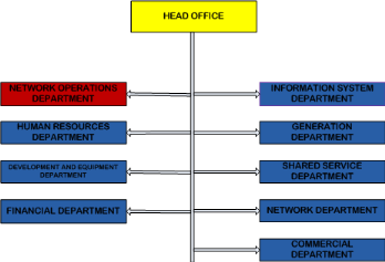
Figure 1: Hierarchical
organizational chart of AESS
1.2.3.2: Organization of the
network operations department
The network operations department is organized into
sub-departments, sub-division and division as depicted in the figure below
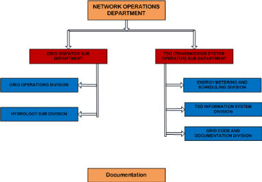
Figure 2:
Organizational chart of the network operations department
The network operations department, future Independent System
Operator/Transmission network Operator (TSO), is presently responsible for
managing all the operations on the electricity transmission network. It carries
out this mission through the following divisions with their respective
functions
· Grid operations Divisions: Located at the Grid Dispatch
center in Magombe, Edea is responsible for supervision and control of the
electricity transmission network, data management, capacity planning and
operations planning.
· Hydrology Sub-division: Located at the Grid Dispatch
center, is responsible for managing and providing information concerning the
water levels and flow rates in the production dams, storage dams and on the
Sanaga and Benue river
· Metering and Scheduling division; responsible for
operations planning, metering, energy accounting and billing.
· Information system division: responsible for the
management (design, maintenance and support) of the information system used in
network operations management as well as the establishment of communication
procedures for the network operations department.
· Grid code and documentation division: establishment and
management of the grid code.
1.2.4: Description of the
AES Sonel network
AESS carries out its mission of generating, transmitting and
distributing reliable electrical energy of excellent quality in compliance with
safety standards through a generation network made up of both thermal and hydro
generating power stations, a transmission network made up of two isolated grids
(the northern grid and the southern grid) and a low voltage distribution
network.
AESS has an up-to-date an installed generation capacity of
about 900MW of which about 88% is hydro and 12% is thermal. Its two main hydro
power stations, Edea and Songloulou with installed generation capacities of
265MW and 384MW respectively are located on the Sanaga River. Another hydro
power station is located in Lagdo, on the Benue River, with an installed
generation capacity of approximately 72MW. These three hydro plants are
supplemented by thermal plants (HFOs and LFOs) located in Limbe, Douala,
Yaoundé and Bafoussam. About 30 aging diesel power stations that supply
isolated centers in the country.
Transmission through the SIG is done using MV (30/15KV) and HV
(225/90KV) power lines. The figure below depicts the whole SIG showing all its
substations and power stations.

Figure 3: The southern
grid [26]
As a summary and as can be seen from above, the SIG has
Ø 29 substations (both 225/90KV and 90/30/15KV)
Ø 2 hydro power stations
Ø 4 Heavy Fuel Oil (HFO) thermal power stations
Ø 5 light Fuel Oil (LFO, Diesel) thermal Power
stations
Transmission through the NIG is done using MV (30/15kV) and HV
(110/90kV) power lines respectively. The figure below depicts the NIG showing
all its power stations and substations
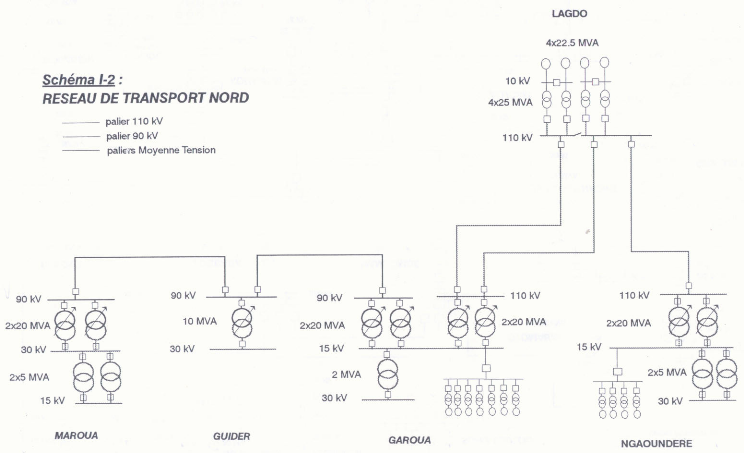
Figure 4: The northern
grid [26]
As a summary, the NIG is made up of
Ø 5 substations
Ø 1 hydro power station
Ø 1 thermal power station
Distribution is done through a highly radial LV (400/380V)
network using MV/LV transformers. AESS presently serves 528,000 customers,
which constitutes 60% of the urban population and 30% of the rural population.
Billing is done using 365 grid connected meters on the northern grid and 1300
grid connected meters MV points on the southern grid.
1.3: Problem location and
description
1.3.1: Existing operations
management system
The entire existing operations management system used by the
network operations department for the management of all the operations on the
electricity transmission network is organized into processes, procedures and
resources.
1.3.1.1: Processes
The processes involved in transmission network operations
management which represent an audit of the main technical activities of the
network operations department include
v Capacity planning: demand planning
forecasting, load flow and stability assessment, technical studies and
enquiries, replacement and refurbishment planning and transmission system
improvement efficiency.
v Operations planning: water flow and load
forecasting, generation scheduling, production simulation including costing and
budgeting, active and reactive power dispatch optimization and transmission
reliability and efficiency.
v Data management: data preparation including
collection and warehousing, energy accounting (power exchange metering
operation), technical performance reporting.
v Supervision and control: grid dispatch
logistics, system real time monitoring and control, power system restoration,
control room resource scheduling and system data and event logging.
v Water resource management: management of
the water level and flow rate in the storage dams, productions dams and the
hydro stations on the Sanaga River.
v Metering and scheduling: billing, energy
and production counting, energy and production costing, energy allocation,
energy balancing, energy flow registration, losses calculation, meter reading
and meter data collection, contract management, meter maintenance and metering
infrastructure management.
v General: training, information exchange, IT
infrastructure maintenance and support.
1.3.1.2: Procedures
There exist well established procedures in operating
instructions manual for all the above processes of which detailed description
is out of scope of this work. For example, for the supervision and control
process, there exist different procedures to be used by the grid
dispatch/system operators in restoring the power system to the normal state
from an alert state, an emergency state, a critical state or a black-out state
and of which there also exist different procedures for restoring the power
system to the normal state from a black-out state resulting from a fault,
insufficiency in production capacity, maintenance intervention, failure of a
major equipment or system e.t.c.
1.3.1.3: Resources
The resources used managing operations on the transmission
network can be divided into human resources and systems (technologies,
softwares)
1.3.1.3.1: Human
resources
The network operations department organized into a grid
dispatch sub-department and TSO sub-department has at its head an engineer
(departmental head).
The grid dispatch sub-department headed by a senior operations
engineer (the sub-departmental head) is structured into an operations division
and a hydrology sub-division. The operations division is made up of 11
employees with a senior electrical engineer at the head (operation divisional
head) and a team of 10 dispatchers/system operators working on shifts of 8
hours per day and 7 days a week while the hydrology sub-division is made up of
about 10 employees with a senior hydrology engineer at the head (divisional
head), 2 hydrology technicians responsible for collecting and analyzing
hydrological data obtained by the other technicians dispersed at the different
hydro stations on the Sanaga river and at the production dams.
The TSO sub-department headed by a senior engineer is
structured into an information system division, a metering and scheduling
division and a grid code and documentation division. The information system
division is made up of a 1 employee (the divisional head) while the metering
and scheduling division is made up of 3 employees with a senior engineer at the
head (divisional head) and a team of 2 technicians to assist the engineer in
his function to carry out the division's mission.
1.3.1.3.2: Systems
Even though most of the underlined processes involved in
operations management cited above are carried out manually, there exist
nevertheless some operations management systems/technologies to aid in their
management.
1.3.1.3.2.1: Existing SCADA
system
Supervision and control of all the operations on the southern
transmission network is done in the control room at the grid dispatch center in
Edea using two SCADA systems deployed on the southern transmission network, the
SKAN4 since 2008 and the LS 2000 since 1979 running in parallel and by a team
of 10 grid dispatch operators working on a shift of 8 hours per day. These two
systems are depicted in the figure below where components of the SKAN4 system
are colored in red

Figure 5: SCADA systems
on the southern grid [1]
This control room depicted in the figure below is made up of a
control desk with two operator stations, each with also two MMI color 21"
Displays, corresponding keyboards and event printers available for display,
printing, control and monitoring of limited parts of the 225 kV/90 kV network
substations and power stations of the southern grid.
The SCADA system supplied by «Landys & Gyr«
consist of redundant (main and back-up) master computers of type LS 2000 to
process information acquired and transmitted from the Substations and Power
stations through the installed RTUs, 7 from type Telegyr 709 as Master RTUs and
12 from type Telegyr 065 as slave RTUs [1]. The information to be processed
includes
§ Critical and non critical alarm signals (AN and AC)
§ Single indications (TS)
§ Double indications (IM and IR)
§ Telecontrols (TC)
§ Measurements (TM)
§ Query signals (QG)
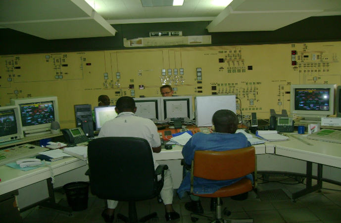
Figure 6: Control room
at dispatch center, Magombe, Edea, Cameroon.
All data from and to the substations and power stations RTUs
are transmitted with 200 Baud Power Line Carrier (PLC) links using the 225 kV
and 90 kV overhead line conductors.
A mimic board is also installed at the control room in front
of the operator desk. Only few information (status indications, alarms and
measurements) acquired directly from the Mangombe Substation are still
available at the mimic board [1]. At the control center the mimic board is
presently used mainly as a passive network single line information board and as
the conventional back up local control panel for the Mangombe 225/90 kV
Substation.
The SKAN4 system supplied by `Siemens' and which runs in
parallel with the LS 2000 system has a similar configuration with the LS 2000
system but consist of 15 TG 805 and 2 TG 065 RTU/data concentrators sending
signals (status, measurements, alarms and control signals) back to a redundant
(master and back-up) set of MMIs for processing through a PLC communication
link. The one operator station with the computers for monitoring, supervision
and control has one keyboard, a mouse and a separate printer for event
printing.
1.3.1.3.2.2: Existing
telecommunication system
The existing telecommunication systems in use for SCADA in
Cameroon (in the southern grid) comprise mainly Power Line Carrier (PLC),
UHF/VHF and Microwave radio links, some Fiber Optic (FO) links installed in
recent time. The telecommunication network is used for transmission of SCADA
data (from some 20 substations and power stations in the 90kV and 225kV
network) and operational voice communication. Except for some links in the
Southern grid, redundant telecommunication paths do not exist.
There are another 5 stations in the north of the country, connected via PLC to
the 90/110kV grid. The PLC links in the northern grid are only used for voice
communication [1]. At present there is no hierarchical structure with regional
control centers i.e. the RTUs send their telegrams directly to the SCC, which
is the high level control center.
The following bullets show the basic SCADA communication
concerns:
· Only some 20 RTUs (out of approx. 30 stations that will
be situated in the 90/225kV southern grid in the future) are connected to the
control center today.
· SCADA data transmission between the RTUs and the
control center is using data channels with transmission speed of 200 bit/s.
For operational voice communication besides the PLC network;
GSM, Cisco IP phones and VHF radio based telephone system are installed for
connection of the SCC and the power stations and substations and other
administrative offices for AESS all over the country. AES SONEL is also using
public telephone lines for the operational voice communication [1].
Besides the usage of PLC, GSM, Cisco IP phones, VHF and
Microwave links, connections to the public telephone services are partly being
used for administrational voice communication from AES SONEL main office with
offices all over the country. Data communication is mostly being done through
emails using an intranet system.
1) PLC (Power Line Carrier) system
Most of the existing PLC terminals are manufactured by AREVA
(former CEGELEC-ALSPA), some by ABB (former BBC). For PLC communication AES
SONEL, is utilizing the frequency range from 40 kHz-500 kHz. The coupling
method used is phase-to-ground coupling [1]. The PLC terminals have a 4 kHz or
2X4 kHz bandwidth respectively, which is used to transmit voice and data
information. Between the substations Logbaba and Koumassi (8.3 km) and between
BRGM and Oyomabang (4 km), each one PLC link is interconnected through coaxial
cables (50 ohm), which are integrated inside the 90 kV overhead line ground
wire. The last part of ground wire between Logbaba and Koumassi is embedded in
the earth with the 90 kV cable. The age of the PLC installations ranges from
some years to over 25 years. Spare parts for the older types of PLC terminals
are expensive or not available any more [1]. Especially for larger stations and
for the interconnection of the power stations to the SCC, the SCADA data
transmission speed of 200 bits/s is insufficient compared to state of the art
SCADA systems. Most of the installed PLC terminals are not operational while in
some cases only voice communication is possible, and the status of some links
is such that they do not provide a reliable transmission medium for the
transmission of SCADA data. Especially with the implementation of standard
protocols (IEC 60870-5-101 and -104) for connection of RTUs to the Control
Center, it is a vital requirement to install reliable data links providing
sufficient data rates.
2) Radio systems
AES SONEL uses UHF/VHF and Microwave equipment in their radio
system. The radio links are used for voice communication to substations, power
stations and to AES SONEL offices (for administrative purposes) [1].Presently,
12 VHF relay stations, with 8 for the south and 4 for the north, cover the
essential routes of HV, MV and LV AES-SONEL electrical
network. Each relay station is corresponds to an independent
sub network and the sub-networks are not interconnected between each other [1].
The majority of the installed radio equipment is manufactured by Motorola of
which some those especially the microwave equipments are non-functional while
some have been abandoned.
3) Fiber optic system
AES SONEL's fiber optic system is presently made up of some fiber
optic cables installed by AES SONEL in the southern grid with the total length
of these fiber optic links summing up to approximately 288 km [1].
4) Telephone system
For operational voice communication within the AES SONEL; PAX
based telephone, GSM and IP telephone systems are connecting the Control
Centers, power stations, substations and administrative offices [1].
For voice communication between the SCC, substations and power
stations in the southern grid of AES SONEL, PAX based telephone systems of
various types and status are installed. The transmission is mainly using the
existing speech channels (4 kHz) of the interconnected PLC equipments between
the substations and power stations. PAX telephone systems are also installed in
the substations and power stations of the northern grid [1].
Operational communication is using not only using the existing
AES SONEL owned telecommunication network, communication with many substations
is also through the Public Telephone Network [1].AES SONEL offices are using
various communication paths for voice and data communication for administrative
purposes (AES SONEL owned as well as Public Telephone Network) such as Cisco IP
phones over the fiber optic links, MTN GSM mobile phones and an intranet system
for data communication over the fiber optic link
1.3.1.3.2.2: Softwares
Apart from some excel sheets used by the hydrology department
in the analysis of hydrological data and the SCADA software, the main software
used by the network operations department is operations and capacity planning
is the QSOM (Quantitative systems for Operations Management) software. It is
used in daily dispatching through unit commitment and the establishment of a
production plan.
1.3.2: The TSO and the new
electricity market system
The process to open-up the electricity markets system in
Cameroon as stated by the new electricity law started after the privatization
of SONEL on the 18 July 2008 by the American AES Corporation. AESS would soon
share the electricity market in Cameroon with Independent Power Producers
(IPP), Independent Transmission Companies (ITCs) and independent retailers
including large customers [2].
The TSO (Transmission System Operator) presently part of the
network operations department would be unbundled from AESS and assigned to a
subsidiary of AESS as stated in the concession agreement. AESS shall conserve
transmission assets, asset owner responsibilities and exclusive rights to
provide transmission services in the scope of transmission while the TSO shall
conserve exclusive right to managing operations on the transmission network.
The TSO would be at the heart of this new electricity market
system as demonstrated in the future hierarchical dispatching structure
below
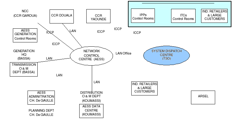
Figure 7: Future
hierarchical dispatching structure [3]
The TSO in this new electricity market structure has as
mission the following [23];
1. Maintain the security and the balance of load flows on the
Transmission system and undertake the management of network power flows, taking
account of exchanges within the interconnected network;
2. Maintain the reliability and security of the Transmission
system, taking account of constraints upon the latter, and implement such
measures as are required to ensure the availability of all the requisite
auxiliary services and the maintenance of a high level of reliability and
security on the electric system;
3. Ensure the optimum use of existing capacity;
4. Manage the take-up of available electricity production at
the lowest possible price, preferably from the national market in case of
exports, in accordance with functions in the general interest to be undertaken
by the Transmission System Operator;
5. Guarantee the availability of management data and ensure
that interested parties receive any information required for the purposes of
billing and the settlement of payments in respect of services provided;
6. Not practice any discrimination between system users,
subject to the limits of available capacity;
7. Supply to the operator of any other system which is
connected to the SONEL system sufficient information to allow the secure,
effective and coordinated operation of interconnected networks;
8. Facilitate the interconnection of systems under the terms
of agreements concluded with any other system operators, participate in the
implementation of rules governing interconnection and supervise compliance with
these rules;
9. Prepare and submit to the Agency an annual estimate of
Generating capacity, Transmission capacity and Distribution capacity connected
to the system; and
10. Identify requirements for interconnection with other
systems, potential Transmission capacity and electricity demand for the next
ten (10) years; this analysis will be updated and submitted to the Agency each
year.
In order to aid the TSO to properly execute its functions and
carry out its mission, AESS is about to put into operation a new PMS (Power
Management System) on the whole Cameroonian electricity transmission network
which also forms part of the context of this work and of which the TSO (more
specifically, the information system division under which i did my internship
and of whom this dissertation concerns) has as obligation under this context
Ø Project ownership responsibilities for the
implementation of the Power Management System (PMS) [23]
Ø Coordination of the proper operational integration of
the PMS in business processes within the AESS [23]
And of which the business integration of this PMS in line with
the PMS project opening memo is the last phase for the complete realisation of
these obligations.
1.3.3: Problem
statement
Based on the concession agreement signed between AES and the
Cameroonian government which requested [2]
1) Modernization of company equipments
2) Modernization of operations management
AESS is about to put into operation a new PMS for the
supervision, control and management of operations on the whole Cameroonian
electricity transmission network. Also in order to ensure security and
reliability in electricity network and market operations, this information
system and the information obtained would be shared between the TSO (system
operator, who has exclusive right to operations management) and AESS
(concession holder, who conserves asset owner responsibilities and has
exclusive rights to provide transmission services).
Faced with a business integration challenge which key to
correct implementation, complete technology transfer, proper operation and the
absolute ownership of this system; AESS has decided study and analyze all the
requirements and aspects for the business integration of this system in the bid
to design specifications and quality assurance measures for efficient business
integration.
In other words, it involves designing quality assurances
measures (requirements and specifications) used in the subsequent development
of a number of quality assurance checklists to ensure the efficient business
integration of this new PMS system. These quality assurance checklists to be
established subsequently would be used to demonstrate compliance with the
defined business integration requirement specifications upon completion of
business integration to ensure correct implementation; full, proper and
sustained operation; complete technology transfer and absolute ownership of
system.
1.3.4: PMS
description
The PMS is an IT-based solution package composed of SCADA
infrastructures on top of which specific softwares are implemented to manage
operations such as planning, supervisory control, energy accounting between the
main nodes of the network e.t.c. More specifically, it is an information system
with information management infrastructures/systems for real-time analysis of
information.
1.3.4.1: Compositional
overview
The new PMS system to be supplied by Siemens (EPC contractor)
and to be business integrated is made up of the following three subsystems with
their corresponding main operational objectives;
1. SCADA/EMS with main operational objective the optimization
of network monitoring and control as well as switching operations for a better
system security and reliability [2]
2. Water Resources Management System (WRMS) with main
operational objective the optimization of the water discharge from the storage
dams for an efficient energy generation and water use in the hydro power plants
[2]
3. Automatic Meter reading/Metering Management System/Energy
Data Management system (AMR/MMS/EDM) with main operational objectives the
provision of reliable metering data from any major grid node of the overall
system network to all entitled stakeholders and the determination of electrical
losses inside the electrical supply system of Cameroon [2].
The compositional overview of the PMS is depicted in the
figure below where real time data/information from the substations and power
stations, the meteo and hydro stations and grid metering points acquired and
processed by their respective hardwares; RTUs/data concentrators,
meteorological/flow meters and grid connected meters; are transported over a
telecommunications network to an interface hardware platform (made up of
servers, switches, e.t.c) to be analyzed and processed by their respective
softwares (information management systems); SCADA/EMS, EDM/MMS and WRMS
softwares.
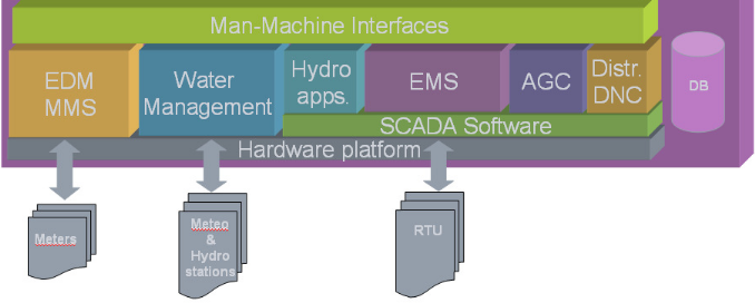
Figure 8: Compositional
overview of PMS system [5]
1.3.4.2: Technical Overview
of PMS
This IT-based solution package is made up of both hardware
(network and control) and software components. The major network and control
components of this PMS to be installed at the different substations, power
stations, hydro and meteo stations and at the system controls centres are
depicted in the figure below showing an overview of the PMS
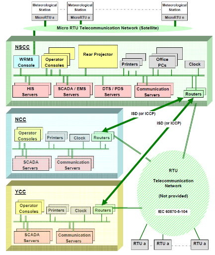
Figure 9: SCADA/PMS
system Overview [5]
All the different data acquisition stations and system control
centers have communication buildings containing all the different
telecommunication equipments such as communication back-up power supplies e.g.
UPS, diesel generator, battery e.t.c; data concentrators; switches; routers and
the fiber optic nodes e.t.c. All sensors and data acquisition equipments at the
different data acquisition stations and grid metering points are connected
through a highly redundant communication network to system control centers for
information and operations management.
All RTUs communicate with the SCADA system through dedicated
data channels. They will have single and double pole statuses, analog and pulse
accumulator inputs, as well as supervisory control outputs for switching of
circuit breakers and isolators as well as raise/lower controls for tap-changing
transformers. These RTUs communicate in [1]
Ø IEC 60870-5-101 (balanced and unbalanced mode)
Ø IEC 60870-5-104 (which is TCP/IP and thus
routable)
Ø dual-port-communication either
o With homogenous protocols (IEC 101-101 / IEC 104-104)
o Or with mixed protocols (IEC 104 main channel / IEC 101
standby channel).
Ø With a future capability of communicating in the IEC
61850
Six different telecommunication systems make up the
telecommunication network associated to this new PMS system for voice and data
transmission and include [1]
Ø OHTL (Over-Head Transmission Line) Power Line Carrier
suitable for voice, SCADA data, corporate data and hotline telephones
Ø GSM fixed mobile facility at each substation
Ø Low Power VHF (Very High Frequency) link to remote
offices
Ø Satellite link to the Garoua office in the North
Ø Microwave link
Ø FOC (Fiber Optic Cable) laid in the way leave of the
existing OHTL's
At the system control centers, functions (information
management systems and their corresponding applications) are compartmentalized
into functional blocks/subsystems with the subsystems implemented on different
servers and the servers distributed along a redundant Local Area Network (LAN).
All the information managements systems (SCADA, EMS, WRMS, MMS and EDMS) and
their corresponding application are critical in operations management and are
hence implemented on dual redundant servers, with one of the servers serving as
a hot standby. All the servers, workstations and network equipments are
interconnected through a redundant fast Ethernet LAN using Ethernet switches.
The most important and fundamental hardware equipments found in all the system
control centers include [5]
§ Application and system servers, performing all the main
data processing tasks and acting as the information reference sources for the
entire system. Critical applications are implemented on dual redundant servers
with one of the servers functioning in the hot standby mode.
§ Multiple workstation consoles with about 3 VDU per
workstation. The workstation consoles are configured for different purposes
(Operator, Engineering, Maintenance, Training e.t.c).
§ Large wall display unit connected to the real-time LAN
to rear-project any displays that would ordinarily be visualized on a
workstation
§ Redundant fast Ethernet 10/100base T switches to
interconnect the different system control center equipments
§ GPS time and Frequency System (TFS)
§ Redundant color and Black & white printers
accessible from workstation consoles for printing of the operating status of
the network anytime an event occurs.
§ Redundant WAN routers for interconnection to other
control centers and RTUs
§ Firewalls for connection to other LAN and WAN such
corporate office LAN, TSO LAN, the internet
This new PMS as depicted in the figure above would be
implemented on three system control centers with the following borders of
operational responsibility [5]
1. A National System Control Center (NSCC) to control and
monitor the entire HV network of AES SONEL in Cameroon, including the outgoing
MV feeders, located in Douala and made up of SCADA and EMS applications.
2. A regional Northern Control Center (NCC) to control and
monitor (in case of break-down of data communication to Douala) the isolated HV
network of the North, including the outgoing MV feeders, located in Garoua and
made up of only SCADA applications.
3. A back-up Yaoundé regional Control Center (YCC) to
control and monitor (in case of break-down of data communication to Douala) the
Yaoundé HV network including the outgoing MV feeders located in
Yaoundé and made up of only SCADA applications.
Also, regional distribution grid monitoring and partial
control would be done at the system control centers and by the regional
distribution control centers (CCRs) in the future.
LAN connections shall be installed between the AESS offices in
Douala (Bassa, Charles de Gaulle and Koumassi), the system control centers and
the TSO offices for information sharing on transmission and distribution
planning and maintenance by AESS as well as on other issues such as energy
dispatch, hydro-thermal scheduling/coordination and water management by the TSO
as depicted in the figure below which shows an principle overview of the PMS
and the future hierarchical dispatching system.
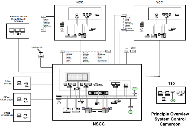
Figure 10: Principle
overview of system control center, Cameroon [1]
Also as depicted in the figure above, there will be an
operator workstation with a three screen Console for each distribution network
((Yaoundé (YCC), Garoua (NCC) and Douala (Remote
console)). For the distribution grid of Douala one operator
workstation and corresponding Console will be located in the same building as
the SNCC. The subsystems (back-up Control Centers, YCC and NCC) for
Yaoundé and Garoua will be located at the AESS building in Mbankolo and
the control building of the Garoua SS/PS. From these workstations the MV
feeders in the corresponding HV/MV substations can be remotely controlled and
supervised.
1.3.4.3: Functional
Overview of PMS
Any time there is a change of state in the network as a result
of an event, signals (alarms, status, measurements and control signals) from
the sensors and actuators locally controlling the different substation and
power station equipments, stored and processed in the RTUs/Data concentrators,
are send over a redundant telecommunications network to the control centers and
then displayed in real time on the workstation consoles of the grid dispatch
operators. This real time data and displays give the operators minute-by-minute
up-to-date information about the status of the network and are also used by the
underlying EMS application modules for real time analysis and computations to
aid them in decision-making.
In addition to some of the supervision, control, data
acquisition, data processing and MMI functions provided by the existing SCADA
system and which would be renewed and extended by the SCADA subsystem of this
new PMS system, this new SCADA subsystem brings in new functionalities such as
[2]
· Topology processor: responsible for analyzing the
open/closed status of network switching devices such as breakers and
disconnectors in order to define the configuration of the network for screen
projection and display.
· Data dissemination: provides the ability to transmit
and receive data (telemetered data, calculated and manually entered data, data
generated by application programs and text data such as alarm messages, event
messages e.t.c to and from other control centers and other computer systems e.g
enterprise management systems or enterprise wide databases, settlement systems
e.t.c.
· Outage scheduler: assist authorized user in scheduling
future outages of power system equipment.
· Information storage and retrieval functions such as
journalizing, energy data collection and calculation, disturbance data for post
mortem review.
The figure below illustrates the different functional
blocks/subsystems of the new PMS and how they interact with each other. The EMS
subsystem has the main task of economically optimizing the utilization of
generation facilities within the constraints imposed by the transmission
network and power/energy exchange contracts or power producers and includes all
the task related to energy purchase, determination of generation cost,
generation maintenance schedules, unit commitment, load frequency control e.t.c
The Energy Management Software in the Power Applications refers to the group of
functions that monitors and controls the generated and exchanged power in the
electric system. In real-time the EMS there would be a significant amount of
coordination between the control center and the various power plant facilities.
System-wide economic benefits are to be achieved when this coordination would
be optimized taking into consideration unit efficiencies, fuel costs and
availability, transmission efficiencies, unit and transmission outages as well
as interchange power availability and price.
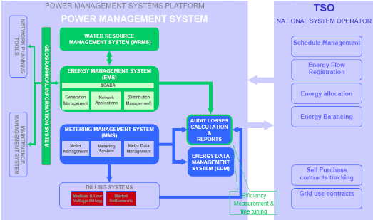
Figure 11: PMS
subsystems functions [2]
The following new functionalities amongst others would be
brought in by the new EMS subsystem in capacity and operations planning and
metering and scheduling [1];
· Load forecast: forecast on demand on daily, weekly,
monthly seasonally (rainy and dry season) and annually basis as well as use the
forecasting model predict initially stream flow between the reservoirs
(Mbakaou, Mape and Bamendjin) and the power plants (Edea and Songloulou).
· Economic dispatch: allocate generation in an optimal
manner among committed units to minimize production cost while respecting
reserve requirements and other constraints
· Load Frequency Control (LFC): to keep controlled area's
frequency, area interchange and system time within pre-defined limits.
· Interchange scheduler: allow the operator to develop
record and maintain the interchange transactions negotiated with other systems
and/or generating companies.
· Reserve monitor: to monitor and account for available
generation capacity and system reserves both system-wise and on a generating
unit basis as well as reactive power reserve to allow voltage control
regulation.
· Hydro scheduling: responsible for determining optimal
operation of the hydro system, taking into account constraints and limits.
· Hydro-thermal coordination
· Energy accounting: for calculating the cost of energy
interchanges based on tariffs defined in the respective transactions.
· Power flow: enable operator to study power flow under a
wide variety of different network situations
· Short circuit analysis: analyze potential short
circuits in network and compute fault currents at selected buses and fault
current contributions from other equipment near the faulted buses
· State estimator: application that processes raw
real-time telemetry data and pseudo measurements to provide real time power
flow solution for the entire network as well as detect and isolate failed or
bad data using either the orthogonal transformation algorithm or the normal
equation with constraint algorithm. Also checks and verifies credibility of
data including limits, consistencies and validity.
· Contingency analysis: application that analyses the
threats to the power network that can potentially result from a credible set of
contingent events under steady-state power system conditions e.g. short
circuit, line loss e.t.c using either the Newton-Raphson's or the fast
decoupled power flow algorithm.
· Optimal power flow: application that enables
optimization in the utilization of the power system generation and transmission
network by using a non-linear programming method to identify operating bottle
necks and the marginal cost of binding constraints in MW dispatch, MVAR
dispatch, fuel cost minimization and remedial scheduling.
· Dynamic stability simulation: solve power systems
dynamic problems such providing accurate simulation models and algorithms to
cover the complete range of transient and time frames, calculation of initial
conditions based on power flow results e.t.c
· Harmonic analysis: for carrying out frequency scan and
harmonic load flow for the determination of network natural frequencies and for
filter design.
· Dispatcher Training Simulator: A DTS (Dispatcher
Training Simulator) for both new and experienced dispatchers with main
functions to train new dispatchers, train dispatchers on advanced EMS
applications, train dispatchers on new EMS applications, testing new EMS
packages and post disturbance analysis.
Apart from the SCADA functions of data acquisition, monitoring
and control of hydro stations, the water management system offers the following
addition functionalities [1]
· Forecasting: water flow and water level forecast at the
different hydro stations on the Sanaga and benue rivers, stream flow between
the reservoirs (Mbakaou, Mape and Bamendjin) and the power plants (Edea and
Songloulou) and inflow into the reservoirs during the discharge and filling
periods using a forecasting model that uses measured historical data from hydro
stations and forecasted precipitated data
· Determine the optimal release of water from the
reservoirs to cover entire dry season taking into consideration the hydro plant
cascading on the river basin using a catchment model
· Scheduling of hydro and thermal plants to optmise
resources especially during critical periods such as the dry season
All energy flows into and out of the HV network and other
energy flows within the energy market would be processed by the MMS [1].
Metering data from all the metering points equipped with metering equipments
(modems/IEDs) would be send over a telecommunications network to the central
MMS. This MMS combined AMR system offers the following functionalities
· Data acquisition
· Data storage and processing
· Data validation
· Data reporting and analysis
There is in general a gap between the physical energy flow, which
can be determined by the meters installed in the electrical grid and the energy
flow determined by the rules of the electricity market. The transformation from
meter data into energy data is a crucial function and a prerequisite for the
settlement of the market interactions between the entitled market participants.
The energy data management (EDM) is a software component that transforms
metering data into energy data by processing besides the metering data also the
schedules of the forecasted data for consumption and electricity provision [1].
The EDM system offers the following functionalities using some mathematical,
programmable macro and scheduling functions with an interface to contractual
and economic information [1]
· Transformation from metering data to energy data
· Depiction of commercial transactions
· Energy allocation
· Energy balancing
o identification of deviations between forecasted consumption
schedule and real consumption
o identification between forecasted supply schedule and real
supply schedule
o allocation of balance energy
· Verification of energy supply from various sources
The figure below depicts the flow of metering data from the
metering system through the energy data management system to the billing
system
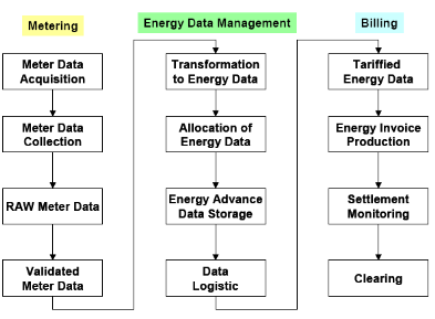
Figure 12: Metering
Management system [1]
The figure above shows clearly the function of an EDM-system
in the context of metering and billing.
1.3.5: The Business
Integration problem
Business integration involves all the processes necessary in
bringing into full and sustained operation equipments (hard and soft) in order
to make sure that they satisfy the needs they were undertaken for during
buying. While the excellent business integration of a system can have
substantial impact on the success of a business, technology alone has no value.
In the case of information systems, business integration includes all the
processes from implementation through transfer and operation to ownership and
the excellent business integration of an information system is indispensable
for
Ø Correct implementation
Ø Complete technology transfer
Ø Full, proper and sustained operation
Ø Absolute ownership
The notion of business integration of an information system
brings in the following important concepts
1. Technology transfer/technology transfer project
management
2. Project implementation/information systems project
implementation
3. Process reengineering
4. Change management
The most successful business integration implementations are
those that meet the business integration requirements and contribute to the
overall success of the business. The successful business integration of an
information system by a business is measured with metrics reflecting the key
performance indicators of the business and not IT metrics.
The socio-technical infrastructure of AESS in the case of
information systems, is made up of obsolete technologies/equipments (hard and
soft), ideas, concepts and technical as well as scientific know-how. A good
example is the LS 2000 SCADA system installed since 1990 by `Landis and Gys'
being used up to today as the main system in supervision and control while
manufacturing of its equipments/components was discontinued since 1999 making
maintenance, upgrade and extension of the system extremely difficult. New
information system technologies/equipments destined for use in operations
management such as for supervision and control, operations planning have faced
serious business integration problems because of this technical, cultural and
conceptual resistance like in the case of the new SKAN4 SCADA system supplied
by Siemens with the aim of renewing and extending the capabilities of the LS
2000 SCADA system as a result of network expansion and increase in the number
of substations, which is not fully operated and has been partially abandoned;
the new daily dispatching software (QSOM) which faced resistance in application
by the dispatch operators e.t.c. This obsolete socio-technical infrastructure
and the concept of routine makes it extremely difficult for AESS to adapt and
change against the reception of new equipments/technology which would impact
the technological, functional and organization aspects of the company.
1.4: Scope of work and
specific objectives
Due to the duration of the internship, this work would consist
more concisely of identifying and studying all the aspects and requirements to
produce specifications and a board of quality assurance measures for (i) total
technology integration to ensure proper and correct implementation of system
equipments; (ii) absolute functional integration to guarantee complete, full
and sustained use of system functionalities and (iii) continual appropriate
organizational integration to ensure total achievement of all technological and
functional benefits, of the SCADA/EMS module (one module of the PMS) for the
southern grid.
CHAPTER 2
GENERAL CONCEPTS AND METHODOLOGY
2.1:
INTRODUCTION
In this chapter, we would be presenting a number of concepts
and techniques which forms the combined methodology used to carry out this
requirement study.
2.2: Systems development
life cycle
The purpose of this a
methodology is to specify a set of well-defined steps or phases, coupled with a
set of clear, measurable exit criteria, for developing and implementing an
information system) [24]. The system development life cycle (SDLC) is a set of
steps that serves as the basis for most systems analysis and design
methodologies.
2.2.1: strengths, weaknesses and limitations
An information system is a set of hardware, software, data,
human, and procedural components intended to provide the right data and
information to the right person at the right time [24]. A system is a set of
interrelated components that function together in a meaningful way, delimited
from its environment (its suprasystem) by a boundary, accepts inputs at its
boundaries and outputs flow back across the boundaries while process is an
activity that changes the system in some way. Of particular interest are the
interfaces, the points at which the various system components communicate or
interact. As a general rule, the more interfaces a system contains, the more
complex the system. The figure below depicts the diagram of a system [24]
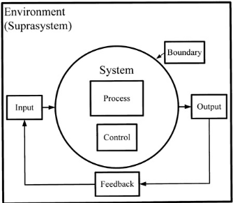
Figure 13: A system
[24]
The system development life cycle methodology acts as a memory
aid by imposing discipline, thus reducing the risk that key details will be
overlooked [24]. Communication is enhanced because the methodology imposes a
consistent set of documentation standards. The steps in the methodology enhance
management control, providing a framework for scheduling, budgeting, and
project management [24]. The tools associated with this methodology that makes
it excellent is that it makes it easier to solve the problem of developing and
implementing an information system and also, increases the likelihood that
significant errors are detected early [24].
Using this method, raises a concern that the system developed
may not accurately reflect the current business environment because the elapsed
time between the initial proposal and system completion can be quite lengthy
(often one or more years). Many methodologies require that specifications be
«frozen» as work progresses from one step to the next, and user
requirements do change over time. Given the fast pace of technology, this
problem is particularly acute with hardware and/or software selected early in
the process [24].
This is a traditional methodology used for developing and
implementing many types of information systems, such as expert systems and
real-time processing systems. Additionally, fourth-generation,
fifth-generation, and objected-oriented languages require modifications to the
traditional approach [24].
The project management life cycle is similar to the system
development life cycle, with stages or phases defining a schedule and
triggering resource allocations. Note, however, that a given project might
encompass several related systems, and a given system might be divided into
several sequential or concurrent projects.
2.2.2: The system development life cycle
methodology (the waterfall method)
The systems development life cycle is sometimes called the
waterfall method because the model visually suggests work cascading from step
to step like a series of waterfalls with sometimes a considerable feedback
between the various steps or phases [24]. A set of steps for solving
information system problems: the basis for most systems analysis and design
methodologies.
The first step is problem definition. The intent is to
identify the problem, determine its cause, and outline a strategy for solving
it [24].
Given a clear problem definition, analysis begins. The
objective of analysis is to determine exactly what must be done to
solve the problem. Typically, the system's logical elements (its
boundaries, processes, and data) are defined during analysis.
The objective of design is to determine how the
problem will be solved. During design the analyst's focus shifts from the
logical to the physical. Processes are converted to manual procedures
or computer programs. Data elements are grouped to form physical data
structures, screens, reports, files, and databases. The hardware components
that support the programs and the data are defined.
The system is created during development. (Note:
Because the entire process is called the system development life
cycle, some experts prefer to use other labels, such as system creation, for
this stage.) Programs are coded, debugged, documented, and tested. New hardware
is selected and ordered. Procedures are written and tested. End-user
documentation is prepared. Databases and files are initialized. Users are
trained.
Once the system is developed, it is tested to ensure that it
does what it was designed to do. After the system passes its final test and any
remaining problems are corrected, the system is implemented and released to the
user. After the system is released, maintenance begins. The objective of
maintenance is to keep the system functioning at an acceptable level
The figure below depicts the various steps to be followed when
applying the waterfall method
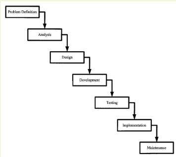
Figure 14; The system
development life cycle is sometimes called the waterfall method
[24]
2.3: Information systems
project implementation
Implementation is the process of completing the system and
turning it over to the user [24]. In the case of an information system, it
includes all the processes involved in site preparation; documentation
preparation; personnel training; system cutover and system release.
Implementation occurs after the system has been analyzed, designed,
constructed, and tested [24].
1. Site preparation: It involves preparing
the work environment, installing the hardware, and configuring any new
equipment to work with existing computers and peripherals. The work environment
includes sufficient space to hold the computer, its peripherals, desks, storage
cabinets, printer stands, and other furniture, and to store such supplies as
paper, ribbons, disks, backup media, forms, cleaning supplies, documentation,
and procedure manuals. Wiring, communication lines, and other physical
connections must be installed. A raised floor might be needed. Security
features might be required [24]. A dependable power supply is essential. Large
computer systems often require custom-designed power supplies. Although most
small computer systems run on standard household current, the equipment can
easily tax the limits of existing wiring (particularly in older buildings), so
rewiring might be necessary. Surge protectors and an uninterruptable power
source (UPS) are recommended for most systems. Air conditioning is another
factor. Computers are heat sensitive, and heat-related problems are difficult
to trace. The computer itself generates heat, and that can add to the air
conditioning load. The cost of inadequate air conditioning is often measured in
excessive downtime and high maintenance costs. Ergonomic requirements are
intended to provide the users with a comfortable working environment. Key
parameters include lighting, glare, airflow, noise, temperature, humidity,
workspace, and the design of the furniture. Many organizations have implemented
ergonomic standards.
2. Documentation preparation and design:
Documentation consists of the specifications, instructions, tutorials,
reference guides, and similar materials that accompany and explain a piece of
software or a hardware component [24]. A complete set of user documentation,
systems documentation, software documentation, and operations documentation
must be available to support the implementation process. In addition to
procedures for performing system tasks, preparing paperwork, entering data, and
distributing output, documentation for backup, recovery, auditing, and security
procedures is also needed. Documentation tells the users how to operate the
system, helps to resolve problems and errors, and supports the training
process.
3. Training: Before the system is released,
the users, system maintenance personnel, system operators, and other people
affected by the system must be trained [24]. The user manual and the written
procedures form the core of the training plan. Initially, the analysts and
other technical experts should show the users how to perform the various tasks.
Gradually, the experts should do less and the users more until the users
clearly understand the system. Following the initial intensive training period,
the users should begin to work on their own, but the experts should be
available to provide quick, accurate technical support. Over time the level of
technical support should decline, but facilities for answering user questions
(e.g., a help facility) should be maintained for the life of the system. In
addition to the primary users and system support people, back-up personnel must
also be trained. Often the primary person trains his or her backup. People
retire, resign, suffer injuries and illnesses, and earn promotions, so there
will be turnover. Training does not end when the system is released; it is an
ongoing activity. In-house training is suitable when the system is developed
internally. The training can be tailored to the system and the organization's
environment, touching on the relationship between the new system and existing
systems and stressing user interests and needs. Unfortunately, users sometimes
undervalue in-house training because they believe the in-house experts will
always be available to provide assistance on request. Third party training
includes vendor-supplied training, developer-supplied training, and training
from independent outside services. Such training is common when a company lacks
in-house information system support or has no on-going training program, or
when a third party develops the system. Some training is done in a traditional
classroom environment. In other cases, the trainer goes to the trainee, perhaps
providing one-on-one or small group training on specific equipment or in the
user's environment. Videoconferencing is an economical training medium for a
relatively brief time (hours, days, or weeks). Distance learning (via satellite
or other communication media) is effective for longer periods (weeks, months,
years). Interactive training software (on tape or CD) is both popular and cost
effective. Computer-based training (CBT) utilizes the computer as a training
tool; for example, an instruction system is a type of expert system that
implements computer-based training.
4. Cutover strategies: System cutover is the
process of turning the system over (or releasing the system) to the user. Some
experts believe that a system should be released any weekday before Thursday,
giving the users at least one day (Friday) to experiment and giving the
installers the weekend to fix any last-minute problems. Other experts believe
that a system should be released on Friday, thus giving the installers three
full days to complete the installation before the users begin working with it
[24].
5. System release: After the system is
installed and stable, it is released, or turned over, to the user. In most
cases, the system release or system turnover process includes a formal user
sign off that implies user acceptance of the system [24]. If the system was
developed in-house, system release marks the end of the developer team's
responsibility. If the system was developed by outside contractors or
consultants, system release implies successful completion of the contract.
6. Post-implementation review: A
post-implementation (or post-release) review should be scheduled some time
after the system is released [24]. During the post-implementation review the
developers should investigate any remaining problems and compare the project's
objectives, cost estimates, and schedules to the actual outcomes. The idea is
not simply to find discrepancies, but to explain them. Knowing why mistakes
were made is the key to improving the organization's analysis, design,
scheduling, and cost estimating procedures. During the post-implementation
review, such general concepts as the design philosophy and the design strategy
should be discussed. The hardware platform, the inputs, the outputs, the
interfaces, the dialogues, the processes, the files and databases, and the
documentation should all be carefully studied to ensure that the system
performs as designed.
2.4: Requirement
engineering
Requirement engineering encloses all those tasks that go into
determining the needs or conditions to meet new or altered systems taking into
account of the possible conflicting requirements of the various stakeholders
such as beneficiaries or users [10]. Also known as systematic requirement
analysis, it is concerned with determining the goals, functions and constraints
of hardware and software systems and is very critical to the success of a
development project. New systems can change the environment and relationship
between people, so it is important to identify all the stakeholders, take into
account their needs and ensure that they understand the implications of the new
system.. Requirement engineering involves the major tasks of requirement
gathering, requirement analysis and requirement recording.
2.4.1: Requirement
gathering
Also known as requirement eliciting, it is the process of
determining what the requirements to meet the new or altered system [10].
Requirements are actionable, measurable, testable, related to identified
business needs or opportunities, and defined to a level of detail sufficient
for system design [27]. Generally for technical management, requirements are
commonly categorized into
Ø Customer/operational requirements: statement of facts
and assumptions that define the expectations of the system in terms of mission
objectives, environment, constraints and measures of effectiveness and
suitability (MOE/MOS). The key customer of the system is the operator.
Operational requirements would define basic needs and answer the following
questions [27]
· Operational distribution or deployment: where
would the system be used?
· Mission profile or scenario: how would the
system accomplish its mission objective?
· Performance and related parameters: what are
the critical system parameters to accomplish the mission?
· Utilization environment: how are the various
system components to be used?
· Effectiveness requirement: how effective or
efficient must the system be in performing its mission?
· Operational life cycle: how long would the
system be in use by its user?
· Environment: what environment would the system
be expected to operate in an effective manner?
Ø Functional requirements: explains what has to be done
by identifying the necessary task, action or activity that must be
accomplished. [27]
Ø Non-functional requirements: requirements that
specify criteria can be used to judge the operation of a system, rather than
specific behaviors. Requirements which impose constraints on design or
implementation. [27]
Ø Performance requirements: the extent to which a
mission or function must be executed; generally measured in terms of quantity,
quality, coverage, timeliness or readiness. During requirements analysis,
performance (how well does it have to be done) requirements are interactively
developed across all identified functions based on system life cycle factors;
and characterized in terms of the degree of certainty in their estimate, the
degree of criticality to system success, and their relationship to other
requirements. [27]
Ø Design/Technology requirements: the requirements used
in buying the system (system design specification requirements). [27]
Ø Derived requirements: requirements that are implied
or transformed from higher-level requirements.[27]
Ø Allocated requirements: requirements obtained by
allocating or dividing a higher-level requirement into multiple lower-level
requirements.[27]
2.4.2: Requirement analysis
and specifications development
Requirement analyst and engineers use several different
techniques in analyzing requirements as well as establishing their
specifications such holding interviews, holding workshops, prototyping, use
cases e.t.c. In requirement analysis and specification development, they use
techniques that include [10];
1) Stakeholder identification: modern technique which involve
identifying the different stakeholders to use the system which encompass direct
system users (operators, organization employing requirement engineer) to
include senior management, back office systems or organizations and other
organizations that can integrate horizontally with organization employing
requirement engineer/analyst. The possible stakeholders of this PMS system in
our context were identified to be IPPs, ITCs, AESS-T, large retailers, large
and small customers, ARSEL and the TSO/present network operations
department.
2) Stakeholder interviews: common method use in requirement
analysis. These interviews help to reveal requirements not previously being
envisaged as being within the scope of the project or even contradictory
requirements. Most commonly, each stakeholder has idea of his expectation or
would have visualized his requirements.
3) Contract-style: a traditional way of documenting
requirements using the implementation plan proposed by the EPC contractor,
Siemens in our context
4) Measurable goals: involves using a set of critical
measurable goals during the requirement analysis during which the level at
which each goal has been attained is continuously being verified.
5) Prototyping
6) Use cases: entails using case studies or examples of
similar systems during the requirement analysis. The National grid and the
NYISO (New York Independent System Operator) were used as case studies in
system operation in our context.
2.5: Process
engineering
2.5.1: Change management
Change Management is the process of requesting, determining
attainability, planning, implementing and evaluation of changes to a
system [11]. The two main
goals of change management include: supporting the processing of changes and
enabling traceability of changes, which should be possible through proper
execution of the process. It is an important process because it can deliver
vast benefits by improving the system and thereby satisfying customer needs.
Change management can also cause enormous problems because it can ruin system
or mix up change administration. In the information technology domain, more
funds and work are put into system maintenance, which involves change
management, than to the initial creation of a system [12].
The change management process includes a set of activities and
deliverables. The six main activities involved in the change management process
are
i) Identify potential change [13]: a potential change can be
identified when a new functionality is required or a problem is encountered
leading to a change request.
ii) Analyze change request [13]: involves determining the
technical feasibility of the change as well as its costs and benefits.
iii) Evaluate change
iv) Plan change: entails analyzing change impact and creating
a change plan.
v) Implement change: entails executing change, propagating
change, testing change, updating documentation and releasing change.
vi) Review and close change: entails verifying and closing
change.
The deliverables of the change management process are
requirements include
Ø Requirement
Ø Problem report: document describing facts and
information related to the problem
Ø Change request
Ø Change log entry: entry consisting of change request,
change technical feasibility, change costs and benefits, change impact
analysis, change planning, test report and change verification.
Ø Change technical feasibility: document indicating
whether or not reliable hardware, software and technical resources are capable
of meeting the needs of proposed system
Ø Change cost and benefits: effort required to
implement and advantages.
Ø Change impact analysis: assessment of the extent of
change
Ø Change planning
Ø Added and changed items
Ø Test report
Ø Documentation: explains, gives instruction for use or
otherwise functions as a major guide to the system materials or system. Can be
material or training.
Ø System release
Ø Change verification: a determination of whether or
not the result of change implementation fulfills the requirements
established.
The meta-modeling technique is used to describe the change
management process. The figure below is a process-data diagram displaying an
algorithm for the change management process with all its activities and
deliverables
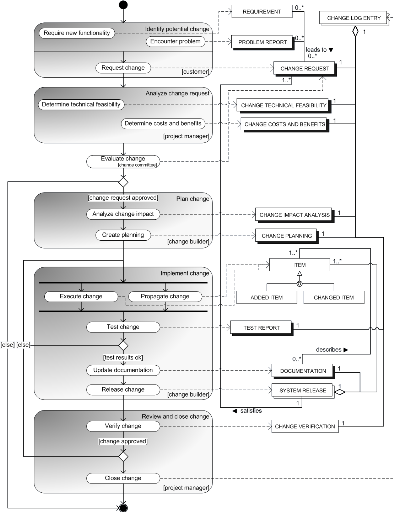
Figure 15: Process data
diagram for the change management process [13]
2.5.2: Business Process
Reengineering (BPR)
Business process reengineering is also known as Business
Process Redesign, Business Transformation, or Business Process Change
Management. Reengineering is a fundamental rethinking and radical redesign of
business processes to achieve dramatic improvements in cost, quality, speed,
and service. BPR combines a strategy of promoting business innovation with a
strategy of making major improvements to business processes so that a company
can become a much stronger and a more successful competitor in the marketplace.
It encompasses the envisioning of new work strategies, the actual process
design activity, and the implementation of the change in all its complex
technological, human resource, and organizational dimensions [17].
Reengineering is an approach aimed at redesigning the way work
is done to better support the organization's mission and reduce costs. It
starts with a high-level assessment of the organization's mission, strategic
goals, and customer needs. Within the framework of this basic assessment of
mission and goals, reengineering focuses on the organization's business
processes--the steps and procedures that govern how resources are used to
create products and services that meet the needs of particular customers or
markets. Reengineering identifies, analyzes, and redesigns an organization's
core business processes with the aim of achieving dramatic improvements in
critical performance measures, such as cost, quality, service, and speed. It
focuses on redesigning the process as a whole in order to achieve the greatest
possible benefits to the organization and their customers. This distinguishes
reengineering from process improvement efforts that focus on functional or
incremental improvement [16].
A key stimulus for reengineering has been the continuing
development and deployment of sophisticated information systems and networks.
Generally business processes are not reengineered simultaneously; they are done
based on the following criteria:
Ø dysfunction: which processes are functioning
the worst?
Ø importance: which are the most critical and
influential in terms of customer satisfaction
Ø feasibility: which are the processes that
are most likely to be successfully reengineered
The five main established methodologies from contemporary
literature used in reengineering business processes and the activities in
chronological order include
Reengineering methodology 1 [22]
1. Develop vision and strategy
2. Create desired culture
3. Integrate and improve enterprise
4. Develop technology solution
Reengineering methodology 2 [19]
1. Determine requirements and goals for the process
2. Map and measure existing process
3. Analyze and modify existing process
4. Design a reengineered process
5. Implement the reengineered process
Reengineering methodology 3 [18]
1. Set direction
2. Baseline and benchmark
3. Create the vision
4. Launch problem solving projects
5. Design improvements
6. Implement change
7. Embed continuous improvement
Reengineering methodology 4 [21]
1. Motivating reengineering
2. Justifying reengineering
3. Planning reengineering
4. Setting up for reengineering
5. As-Is description and analysis
6. To-be design and validation
7. Implementation
Reengineering methodology 5 [20]
1. Preparation
2. Identification
3. Vision
4. Technical and social design
5. Transformation
A consolidated methodology has been developed from the above
five methodologies by taking into consideration their common attributes and
differences. This consolidated methodology is depicted in the process flow
diagram below, which shows the main processes and the activities involved
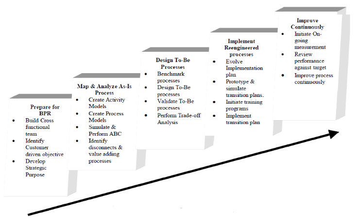
Figure 16: Business
process reengineering consolidated methodology [7]
2.6: Technology transfer
Technology denotes the broad area of purposeful
application of the contents of the physical, life and behavioral sciences [25].
Technology transfer is a long and complex process of innovation, that is, a
process of adaptation and change. Technology transfer projects often occur
where the recipient culture (technology-pull side) is different from the source
culture (technology-push side) and therefore generally long, complicated and
extend over an average of two to four years [25].
Technology transfer is composed of horizontal and vertical
technology transfer and takes place at the following two main levels [25]
1. Development level: characterized by the following
development and research phases; discovery phase, create phase leading to an
invention, substantiate phase, development phase leading to a prototype and an
engineering phase leading to a functional technological system which may be a
process, an intellectual concept, a hardware product e.t.c
2. Impact level characterized by how the technology is going
to affect its destination
Technology transfer might come as a result of a company
strategy to improve on process management by buying a new technology and of
which is the case of AESS in the context of this work or the ordinary
commercial operation of a firm e.g. technology vendors who regularly transfer
technology to their clients and of which is the case of Siemens (EPC
contractor) for this PMS project in the context of this work.
An efficient technology transfer can be obtained by first
answering the following questions [25]
ü What aspects of the technology are transferred in the
transfer project? How can they be conceptualized?
ü How can the overall system within which the transfer
occurs be represented?
ü What transfer model exist that can be used to develop a
particular design?
ü What steps are required to ensure efficiency in the
transfer and the technology appropriateness (integration) to the new context
and specific destination point?
The following are the factors involved in a decision-making
process in the pursued of a technology transfer strategy by the technology-pull
side (purchaser, recipient or destination point) and the corresponding decision
phases they affect. These phases and their deciding factors form in other words
the steps used in ensuring an efficient and complete technology transfer
(stages in a technology transfer project)
1. Needs and opportunities in the development plan phase
2. Technology transfer project analysis (technical
feasibility, market analysis and financial analysis) for the implementation
strategy phase
3. Technology transfer project evaluation and selection in the
portfolio of project phase
4. Technical availability, cost and socioeconomic conditions
in the design and management of the technology transfer project phase.
The technology transfer project analysis at the implementation
strategy phase with feasibility studies entails
a) Needs assessment, that is, technical requirements for
responding to a specific market demand and which would spell out linkages
between users of product, producers or the competition
b) Impact on of the technology on destination
c) Technical feasibility of transfer, that is, feasibility in
terms of current processes, comparative analysis with other technologies,
equipments required human resources and skills needed, training requirements,
contract and transfer-management conditions, requisite modification to existing
processes, impact on working relations and functional linkages, impact on user
and consumer behavior relative to final product.
Design and management of the technology transfer project is
the last phase of the process and is one of the other main ways/mechanisms in
which technology transfer takes substance apart from the purchase of a direct
license.
2.7: Technology transfer
project management
Management of a technology transfer project includes all the
phases of design, planning and implementation of the transfer [25]. Unlike the
classical phases of project management through which a technology transfer
project also proceeds, managing a technology transfer project involves training
and human relational learning with all the complexities it can entail.
Technology transfer project management is all about overcoming conceptual
resistance, technical resistance, economic and financial resistance, as well as
cultural resistance which characterizes the behavior of all companies and
businesses towards the coming of a new technology [25].
The management strategy for a technology transfer project
depends on the following variables [25]
· Nature of the origin and destination systems; the
socio-technical nature of the systems involved in the transfer.
· If it is a `technology-pull' problem involving
socio-technical adaptation or a `technology-push' problem, involving building
bridges across boundary lines
· Type of technology involved; hard or soft: the
hard/soft metaphor applies to the technology transfer as well as to the type of
resistance offered/boundaries encountered; the more scientific or conceptually
intricate a technology is, the more changes integrating it would require at the
destination end, the greater the degree of innovation it would require and
hence the softer the technology would be while the more extensive the machinery
and equipment associated with the technology are and the more they operate on a
stand-alone basis, the more automated the technology is, the freer it is of the
context and social sphere into which it is being placed, the harder the
technology would be. Hard technologies or the hard components of a technology
are fairly easy to transfer across hard boundaries (poorly developed
destination systems in technology) while soft technologies or the soft
components of a technology like information systems, technical know-how of a
technology require careful integration
· Technical limits beyond which technology is no longer
efficient
· Relative hardness of the boundaries/resistance:
resistance to change is exhibited in the form of boundaries/barriers, keeping
out change from the outside system.
· Relative hardness of the technology
· What would be transferred in the technology transfer
i)Transferring hard technologies across hard boundaries are
conditions surrounding some turnkey based projects and have a greater chance of
succeeding e.g. dam in Chine built by North American companies; (ii)
transferring hard technologies across soft boundaries e.g. Canadian nuclear
plant in Italy; (iii) transferring soft technologies across soft boundaries
where the strategic issue for transfer project management is in terms of
`technology-pull' (the receiver's objective) and finally, (iv) transferring
soft technologies across hard boundaries which is the most complex from the
technology transfer management perspective and where the central problem is the
relative impermeability of the boundaries which sets up resistance to
socio-technical change and makes innovation difficult.
Transfers concerning soft technologies or soft components of a
technology need careful integration and pre-planned strategies, since they
require substantial adjustments on a company's social system (e.g. its
organization) while the transfers across hard boundaries would need intervening
institutions as bridges between the source and destination as they would have
to cross hard boundaries and thus overcome strong resistance to transfer.
2.7: Adopted methodology
A combined methodology which included concepts and methods
from the systems development life cycle, information system project
implementation, process engineering, and technology transfer and technology
transfer project management was adopted.
Actually,
1. The systems development life cycle and the information
system project implementation concepts and methodologies detailed the stages
that would be crossed for the implementation of the PMS system equipments and
were used to obtain some of the requirements
2. Requirement gathering techniques were also used to obtain
the rest of the requirements
3. A link between the requirements was being established
4. The requirements were then grouped into the technological,
organisational and functional dimension
5. Then, techniques and concepts in technology transfer,
technology transfer project management, process reengineering, change
management and requirement analysis and specifications development were being
used to develop the specifications for the requirements.
Infact,
1) In order to make sure Siemens implement PMS equipments as
specified, we need to
o Identify all prerequisites for implementation
o Set up the proper organization for PMS implementation taking
into account AESS internal constraints Vs Contractor planning.
o Identify unit test requirements (FAT)
o Identify integration tests requirements (SAT)
o Identify system test requirements (SAT)
2) The most important responsibility of AESS during
implementation is to
o Provide system data
o Validate system data
3) Business process reengineering would enable AESS to adapt,
redesign and change (reengineer) its organization and business (existing
socio-technical setting) to properly and completely integrate the PMS system
equipments in operations management through a
o PMS Impact study : identify impacted business units/BU
departments/people/detect people adequacy to function
(quantitative/qualitative)
o First round of organizational change : new
structure/units/function/ assignment/mission
4) Proper use of PMS equipments during their life cycle by all
people involved in system operation and system management would be ensure by
ensuring efficient technology transfer during business integration through
o Training of users
o Training program to organize training of users
o Keep user documentation available to every users
5) Full and sustained operation of implemented PMS equipments
would be ensured by
o Setting-up a maintenance policy
o Making sure all people involved in system maintenance are
trained
o Making sure training program include training of
maintainers
o Making sure maintenance strategy/policy and contractor
support entry are shared
o Keeping system documentation available for every one
2.3: Conclusion
We have adopted a methodology we are going to use in carrying
out this requirement study of which we will present the results in the next
chapter based on state-of-the-art techniques and concepts in requirement
engineering, technology transfer, technology transfer project management,
change management, information systems project implementation and business
process re-engineering.
CHAPTER 3
RESULTS
3.1:
Introduction
In this chapter, we present the results of this work by first
presenting the requirements and then their specifications. The chapter then
finishes by presenting the implications of the requirement specifications in
quality assurances measures for efficient business integration.
3.2: Requirements for PMS
business integration
The following requirements were obtained
1. Technological integration requirements
1.1 pre-requisites for implementation (site preparation)
1.2 quality data for system (data requirements)
2. Organizational integration requirements
2.2 Business process reengineering
3. Functional integration requirements
3.1 systems rollout
3.2 training
3.3 maintenance and support
3.4 documentation
3.2: PMS business
integration requirements specifications
3.2.1: Technological requirements
3.2.1.1: Pre-requisites for
implementation
The
pre-requisites for the implementation of this new SCADA/EMS system are
classified under three main categories
1) Human resources
2) Civil and construction works
3) Telecommunication infrastructure
All the above pre-requisites are critical and must be verified
for existence and functional effectiveness before the implementation of this
new system.
3.2.1.1.1: Human Resources
This involves the verification of human resources in terms of
existence, qualifications for recruitment and preparation for training for the
following main functions
§ Implementation
§ Project Handling and Follow-up
§ System Operation and Business Integration (BI)
3.2.1.1.1.1: Implementation
Human resources needed for OJT for the following
implementation functions
- Tests (FAT, SAT I, SAT II, functional and availability test)
and commissioning
- Site activities (substation adaptation works, site
adaptation works, civil work and construction work e.t.c)
- System platform erection and installation
- Data entry, database generation and software adaptation,
data population and data preparation
- System development, preparation and delivery
3.2.1.1.1.2: Project Follow-up and Handling
Human resources (both AESS staff and experts) for project
follow-up and for the handling of project functions.
The following experts are needed for the project
- Project Director for overall project coordination,
project management and to ensure implementation of overall systems
- Project Management assistant to assist project
director in his functions
- Consultants (team of experts) to assist in project
engineering, supervision of works, organization-change management, IT
integration and support on information systems rollout
- SCADA/EMS expert for engineering and supervision of
SCADA/EMS
- Power System expert for support in transmission and
distribution system design and operation and in system modeling
- Organizational expert for support in commissioning
and training, process re-engineering and change management
- Data warehouse expert to implement energy master
data referencing and integration data flow, support test data preparation and
support data cleansing and data populating
AESS staff for the steering committee responsible for the
strategic follow-up of the project and made up of members from the project
direction, EPC contractor project director, TSO, COO, DSI and the DDE.
AESS staff for Owner engineering functions which include
- Project engineering functions including confirming
specifications in tender documents forming the basis for performance
requirements; approval of contractor's plan to meet performance criteria;
approval of detailed technical design and drawing provided by contractor;
follow up of hard and software development and particularly the development of
models; checking system conformance with functional specifications; agreement
on testing procedures with contractor; witnessing factory tests in the
manufacturer's work before acceptance for shipping to site; agreement on
equipment configuration in transmission and generation stations, river basin
and customer's premises representing scope of works at each location
- Project management functions including analysis of
project risks; project completion report; detailed definition and monitoring of
KPIs; ensure respect of cost and schedule; preparation of a detailed project
control program; project office responsibilities such as accounting, supply
chain follow up and reports preparation; project coordination, logistics,
meeting organization, communication, readiness and circulation of documents;
overall detailed planning of AES-SONEL workload during the work statement with
the contractors
- Supervision of work functions including migration
of project implementation risks; ensure readiness of technical documentation
and as built drawings; commissioning and warranty run monitoring; witnessing
site test and acceptance of performance of system as built; check buildings;
quality assurance during implementation (AESS construction and safety rules);
supervision of buildings, fittings, and furniture of national and regional
control rooms and IT rooms
- Support on information systems rollout including
preparation of trial and takeover of system; prepare testing and commissioning
certification of the system; support in change management implementation,
training supervision, new process and new procedures drafting in relation with
user departments; detailed design of change management implementation road map
to accommodate new systems; draft definition of borders of operational
responsibilities; support in IT integration, database design and integration,
data referencing and cleansing; ensure PMS efficiency measurement
implementation, suitable data modeling and flows integration in the data
warehouse; AES-SONEL PMS platform overall architecture during work statement
with EPC contractor, taking into account PMS operational environment and
interfaces with existing and future corporate systems (billing system, GIS,
planning tools, maintenance management tools)
AESS staff for the project direction responsible for the
operational direction of the project to achieve the corporate objective on
behalf of the steering committee and composed of sub-directions from the
following departments
§ Shared service department (DSG)
§ Development and Equipment department (DDE)
§ Network department (DRes)
§ Information system Department (DSI)
§ Commercial Department
§ Business Integration sub-direction
With each sub-direction made up of a sub-directional
head, technical correspondent(s), project head(s) and expert user(s)
3.2.1.1.1.3: Systems Operation and Business Integration
(BI)
AESS staff for the following functions
- Deputy Project Director for BI teams coordination,
ensure information system integration for corporate objective effectiveness and
overall IT overseer
- Network team leader to implement BI for network
operations and assist in the supervision of the SCADA/EMS project
- Planning and Dispatching team leader to implement
BI in planning and dispatching and modeling overseer
- IT integration team leader to provide and implement
IT infrastructure for the overall PMS system
AESS staff for Business Integration functions in
v Planning and dispatching such as collection of
network technical parameters, check accuracy of forecasting model, strategic
outlook of business transformation through business integration (apply APEX
deliverables), modeling overseer e.t.c
v Network Integration such as master data
preparation, confirm interoperability of existing switchgear, issues connected
to operation and maintenance, communication to all stake holders within the
network e.t.c
v IT integration such as implementing data center and
IT control rooms, implement telecommunications over IP (fiber optic, MAN/LAN
cabling, GSM, GPRS and satellite), ensure AESS IT maintenance capabilities,
provide data referencing and conversion platforms (Dataware house and GIS)
AESS staff for System Operation and day-to-day system running
functions in
v Planning and dispatching
v Network operations (supervision and control, interventions,
maintenance...)
v IT
3.2.1.1.2: Civil, Construction and adaptation Works
Some civil, construction and adaptation works which are the
responsibilities of AESS and are required for the implementation of this new
system include
Ø All external works such as paved areas, car parking,
landscaping and construction of a higher perimeter wall and a guardhouse
respectively around the premises and at the entrance to the Bali compound
building except for everything that concerns the installation of the generating
set.
Ø Construction of a second transformer substation in
the NSCC yard behind the building
Ø Provide connection between the two transformer
substations and the AC room of the NSCC for the contractor to connect to the
power supply
Ø Painting of the external walls of the first and
ground floor of the Bali building to harmonize with the entire building
Ø Refurbish the entire building both internally and
externally including the roof in time so as to intervene as little as possible
with the works to be executed by the contractor.
Ø Refurbishment and equipment of the room CCR (Centre
de conduit de reseau) room in Douala
3.2.1.1.3: Telecommunication Infrastructure
The telecommunication infrastructure associated to the SCADA
system responsible for voice and data communication is of full responsibility
of AESS. The functional effectiveness of the telecommunication infrastructure
is critical for the implementation of the new system. The following are very
critical for the system implementation
Ø Connection of FO between the NSCC and the various
users-de Gaulle, Koumassi, Bassa e.t.c
Ø Connection of multiple sites in Oyomabang, Bafoussam
e.t.c
Ø Connection of FO to NCC and YCC
Ø Voice recorders at the NSCC, YCC and NCC
Ø Surveillance of RTU and process by surveillance of
FO
Ø Installation of radio communication in NSCC, YCC and
NCC
Ø Installation of Telephones and internet in the Bali
building, NSCC, NCC and YCC
There are six telecommunication networks (PLC, OHTL, GSM,
Satellite, microwave and VHF radio) associated to this SCADA system. The figure
below shows the actual state of the FO and PLC networks of the AESS SIG
3.2.1.2: QUALITY DATA FOR
SYSTEM
The data for the new SCADA/EMS system can be classified into
four main categories
1) Organizational Data
2) Reference Data
3) SCADA Process (Application) Data
4) EMS Process (Application) Data
3.2.1.2.1 Organizational Data
This is data for system organization. It includes
3.2.1.2.1.1 Transmission Network Plan
· One line diagram of the whole SIG showing all Zones,
Branches, Areas and Interconnections as well as all the hydro and thermal
generating stations, loads, busbars, switches (isolators, disconnectors and
circuit breakers), capacitor banks, transformers e.t.c
· One line diagram of all the existing transformation
substations and generating stations substations showing load centers, busbars,
switches (isolators, disconnectors and circuit breakers), capacitor banks,
transformers e.t.c
· Name; location; characteristic voltage levels; number
of feeders, transformers, capacitor banks, circuit breakers, isolators,
disconnectors, busbars and other major components of all transformation
substations and generating stations substations of the SIG
3.2.1.2.1.2 Telecommunication Network
Infrastructure
· Telecommunication Infrastructure Plan showing all the
different telecommunication networks (FO, GSM, VHF radio, PLC and microwave) on
the SIG used in association with this new SCADA system for data transfer as
well as for voice and data communication
3.2.1.2.1.3 Profile Data for System users (System
Operators and System Administrators)
Data defining all the logging parameters of system users
· Names
· User type: Normal system user, System operator or
System administrator
· Profile access method (knowledge-based e.g. password,
possession-based e.g. badge...)
· level of authorization such as Area Of Responsibility
(AOR), operation mode (read, write...), application access e.t.c
3.2.1.2.1.4 Generation System
Owner Data
Data from all generator/generation power station owners
concerning their generating facilities and would include
· power station owner e.g. KPDC
· power station owned e.g. Dibamba
· power station type e.g. Heavy Fuel Oil (HFO)
· available generation capacity in MW, MVA and MVar e.g.
86MW
· power station connection point, that is connection
substation e.g. Ngodi Bakoko substation
· power station location in terms of branch, zone, area,
town e.g. Douala, Littoral zone, Nyalla area e.tc
3.2.1.2.1.5 Transmission
System Customer/End User data
Data of the different transmission system customers (end
users) concerning their consumption facilities and would include
· Customer type (HV, MV or LV customer) e.g. MV
· Customer name e.g CIMENCAM
· Customer location (branch, zone, area, town) e.g.
Douala, Littoral zone, Bonaberi area e.t.c
· Connection point (substation) e.g Bonaberi
· Consumption in terms of MW, MVA and MVar e.g. 7MW
3.2.1.2.2 Referential Data
This is technical information of all network assets/equipments
both electrical, control and IT network assets. This information is very
important for maintenance (both predictive and corrective maintenance), system
operation (in performance and limitation check of systems and equipments) and
in asset inventory management.
3.2.1.2.2.1 Transmission System Electrical Network
Assets
This includes all up-to-date technical information obtained
from the manufacturers, nameplates and technical catalogues of all the
electrical network assets of the SIG concerning their technical
characteristics, makes and models, performance and limitations including
Ø Transformers
Ø Switches (reclosers, circuit breakers, disconnectors,
isolators, fuses)
Ø Transmission lines
Ø Capacitor banks
Ø Busbars
Ø Generators
Ø Protection devices
Ø Auxiliary equipments such as UPS, batteries,
rectifiers, battery chargers e.t.c
Ø Loads e.t.c
For example, referential data for a transmission line would
include
· Origin e.g. Logbaba
· Destination e.g. Bekoko
· Cable structure e.g. Almelec
· Dimension e.g. 570mm
· Length e.g. 41.50km
· Voltage e.g. 225Kv
· Transmission line capacity in MW, MVA and MVar
And for each transformer, information such as
· Location
· Manufacturer (make and model)
· Voltage level xtics
· Power
· Ohms
· Reactance
· Regulation
· % overload supported
· IP (protection index)
3.2.1.2.2.2 Telecommunication Network System
assets
Technical and performance data of all the telecommunication
and IT network assets including
Ø Fiber Optic cables
Ø Switches, routers, servers, monitors and RTUs
Ø GSM
Ø GPRS
Ø Radio
Ø Satellite
Ø Microwave
Ø Power Line Carrier
3.2.1.2.3 SCADA Process
Data
Data necessary for the development of the teleinformation plan
for the SCADA system. They constitute data points for the SCADA system and can
be classified into four main categories
1) Controls/Commands
2) Status
3) Alarms
4) Measurements
3.2.1.2.3.1 Controls
Data on all substation equipments per substation of the
southern grid that receive controls/commands and the nature of control/command
forming control data points and would include
· Substation name e.g. Bekoko
· Equipment e.g. transformer, capacitor, busbar e.t.c.
· Equipment voltage e.g. 225kV, 90kV
· Command equipment e.g. circuit breaker, isolator,
disconnector, tap changer
· Command type e.g. open/close in the case of a circuit
breaker, raise/lower in the case of a tap changer
3.2.1.2.3.2 Status
Status information of all important substation equipments as
well as substation command equipments per substation for all the substations of
the southern and would include
· Substation name e.g. Bekoko
· Equipment voltage e.g. 225kV, 90kV e.t.c
· Equipment e.g. generators, switches, tap changers
e.t.c
· Status type e.g. on/off or local/remote in the case of
a switch, manual/auto or local/remote in the case of a tap changer, run/stop in
the case of a generator e.t.c
3.2.1.2.3.3 Alarms
Alarms to indicate all
critical (alert or emergency) network situations such as faulty equipments,
confirmation of a command send, faulty operation by a system user, surpassing
limit conditions for all the substations of the southern grid forming the alarm
data points and would include
· Substation name e.g. Bekoko
· Equipment voltage e.g. 225kV, 90kV e.t.c
· Equipment e.g. transformer, capacitor bank e.t.c
· Alarm type e.g. breaker faulty, transformer overloaded
e.t.c
· Alarm condition e.g. critical, non critical e.t.c
3.2.1.2.3.4 Measurements
Data concerning all measurements to be taken including
voltage, power (active, reactive and apparent), energy (active, reactive and
apparent), frequency, current, temperature as well as the measurement points
per substation for all the substations of the whole southern grid and should
include
· Substation name e.g. Bekoko
· Metering points e.g. capacitor bank, feeder,
transformer, busbar e.t.c
· Measurement type e.g. temperature, power (MW, MVA,
MVar), frequency, current, voltage and energy (MWh, MVAh, MVarh)
3.2.1.2.4 EMS Process Data
This is process data required by the EMS subsystem to carry
out its computations and analysis.
3.2.1.2.4.1 Generation
Process Data
All information and data on the
status, generating capacity and availability of the different Generating
(Power) stations connected and supplying power to the transmission system of
the southern grid for dispatching and planning and should include information
such as for each generating station
· Power station e.g. Edea
· Power station owner e.g. AESS
· Generation type (thermal or hydro)
· Production cost
· Available generation capacity
· Installed generation capacity
· Power station connection point
· Power station location
Also for each of the different
generating stations, information for the different generating units such as
· Generating unit
· Generating capacity
· Base MVA
· Base MW
· Capacity limit (overload supported)
· Generation voltage
· Availability (help in defining the capacity factor of
the generating unit and its usability: important at the profiling stage of
maintenance programming)e.g. 90%, 50% e.t.c
· Generating power factor e.g. 0.90. 0.80 e.t.c
3.2.1.2.4.2 Network
Application Process Data
Data and information needed by the different applications of
the network application module to perform their respective computations and
decision-aid functions. It involves all the data for operation management and
business transactions. It involves all the details in terms of
Ø Substation data
Ø Transmission line data
Ø Bus Station data
Ø Load and load factor data
Ø Towns, Zones, Areas and Branches data
Ø Protection system data
Ø Generation and transmission cost of the different
transmission system users
Ø Reliability, forecast and stability data e.t.c.
3.2.2 Organizational
requirements
3.2.2.1 Operations
reengineering
These involves an impact study for the re-engineering
(rethinking and redesign) of all the business/operations processes as a result
of the new functionalities introduced by this new SCADA/EMS system and the new
electricity market system structure.
The main objective of the TSO is to operate the Cameroonian
electricity transmission network in its most secured and reliable state (normal
state) using the functionalities of the SCADA/EMS subsystem of the new PMS
system to
Ø Anticipate potential problems
Ø Apply preventive measures
Ø Quickly respond to actual problems
Operations reengineering requires the following main issues
I) Establishment of a grid code containing
· Roles, Responsibilities and linkages of market
participants (generators, transmitters and distributors), defining the
rights and obligations of the participants regarding the operation of the
Transmission system
· Terms and conditions for connection to the
Transmission System , defining connection conditions (for generators,
distributors and end-use customers), technical design and construction
requirements applicable to the service providers as well as the Transmission
System development process and methodology
· Terms and conditions for providing transmission
network and system operation services
· Operation and quality standards for
transmission and transmission system operation, focusing on quality
standards with respect to product (electricity) quality, Quality of supply and
system reliability requirements
· Scheduling and Dispatch arrangements for
generation and transmission network
· Commercial Rules related to Dispatch, energy
balancing and Settlement calculations in the Bilateral Contract
Model
· Pricing principles and tariffs for the
provision of transmission and transmission system operation services,
specifying the objectives, structure and the methodologies employed in
transmission tariffs.
· Information (exchange) requirements for
transmission system operation, specifying the information requirements
and obligations of all the parties associated with system operation.
· Grid Code Governance, detailing all
aspects of Grid Code governance and in particular the procedures for
rules change.
II) Operating policies as well as newly established operating
rules and procedures for all of the processes involved in the following
operations
· Monitoring operations: real time supervision and
control
· Transmission and dispatching operations: transmission
operations, scheduling operations and dispatching operations
· Back-up operations
.Established operating procedures for real time supervision
and control (monitoring operations) for example should include
1. Monitored system conditions
o Transmission facility flow
o Stuck breaker
o Actual voltage
o Post-contingency voltage
o Reserve conditions
o Stability limits
o Area control error
o System frequency
o Communication, computer, control and indication
facilities
o Neighboring systems
o System separation
o Over-generation
o Severe weather conditions
2. State definition for the different operating states for the
different system monitored conditions
o Normal state
o warning state
o Alert state
o Major emergency
o Restoration
3. State criteria for power system existing in underlined
operating state
o Pre-contingency flow criteria
o Post-contingency flow criteria
4. Actions of the TSO, transmission system owner and other
actors to power system state when
o State is declared by TSO
o State is declared by transmission system owner
o State is declared by generators and customers
III) New communication procedures based result of the new
communication systems and should include the following details
(non-exhaustive)
· When a communication system to be used and by who
· How should a communication system be used
· Aspects of the communication system to be used
· When communications should stop
For examples, when an Alert State or Major Emergency State
occurs: the TSO Shift Supervisor shall communicate with the affected
transmission owners to determine the nature of the problem and to make a
preliminary estimate of the assistance required. The Shift Supervisor shall
then notify all transmission owners via the Emergency Hot Line System that an
Alert State or Major Emergency State exists. After this notification, all
normal or routine calls on the direct dial telephones between the Shift
Supervisor and the transmission owners shall cease. These lines shall be used
only for communications between the Shift Supervisor and the affected
transmission owners. And then, when the Restoration State occurs: the Shift
Supervisor shall notify all transmission owners via the Emergency Hot Line
System that a Restoration State exists. After that notification, all normal or
routine calls on the Direct Dial telephones between the Shift Supervisor and
the transmission owners shall cease. These lines shall be used only by the
Shift Supervisor and the affected transmission owners to communicate
information about the restoration process. The transmission owners shall use
the Emergency Hot Line System to communicate completion of restoration steps to
the Shift Supervisor.
3.2.2.2 Organizational reengineering
It entails an impact study on the re-organization and
re-structuring for the following different units
(services/department/sub-departments/divisions) of AESS to be impacted by this
new system for re-organization
1. Generation department
1.1. Hydro power stations: Edea and Songloulou
· Operation divisions
· Electrical division: light current and heavy
current
· Mechanical division
· Performance and reporting
1.2. Thermal power stations: Limbe; Dibamba; Oyomabang I and
II; Bassa 2 and 3; Bafoussam and Logbaba I and II
· Operation divisions
· Electrical division: light and heavy current
· Mechanical division
· Performance and reporting
2. Networks department
· SCADA and telecommunications division
· Performance and reporting division
· HV/MV line maintenance division
· Substation operation and maintenance
· Automation and protection
3. Networks operation department
· Grid operations division
· Hydrology sub-division
· Metering and scheduling division
· Information system division
· Grid code and documentation division
Re-structuring and re-configuration (organizational
reengineering) should be done in terms of
ü New units created
ü Mission (objectives)
ü Resources: human and technology
ü Principal activities
ü Training
ü Job positions (new job positions)
ü Job description
3.2.3 Operational
requirements
3.2.3.1: Systems rollout
It entails the establishment of a migration/cutover strategy
from managing operations using equipments (hard and soft) of the existing
operations management system to managing operations using equipments (hard and
soft) the new PMS which contains
· Migration/cutover conditions
· Migration/cutover approach and a procedure with
advantages and disadvantages
· Migration plan
Migration/cutover could be
1. Direct cutover: Also called crash cutover or
abrupt cutover, where the old system is discontinued on a predefined date
(often corresponding to the start of a new accounting period) and the entire
organization switches directly to the new system. Direct cutover is risky
because, if the new system fails, returning to the old system is virtually
impossible. This strategy is relatively inexpensive, however, and it tends to
promote user acceptance since there is no old system to serve as a basis for
comparison..
2. Parallel operation: where the old
and the new systems run in parallel for a time and which tends to be the most
effective when a computer-based system replaces a manual (or partially manual)
system because concurrently running two computer-based systems is very
expensive and which gives makes an excellent choice when data accuracy,
security, and/or reliability are important concerns.
3. Gradual cutover: which is a combination of direct and
parallel cutover and where the idea is to run the new and old systems
concurrently and gradually increase the number of transactions handled by the
new system. Actually here, data is not processed twice; instead, some
transactions are processed by the old system, some are processed by the new
system, and the percentage sent to the new system gradually increases until the
old system fades away.
3.2.3.2: Training
Well-organized and proficient training of system users
(administrators, operators and maintenance personnel) to enable them to carry
out effective operation and maintenance of the SCADA/EMS system hardware and
software as well as the telecommunication equipment after the taking over is
the most efficient way of ensuring
· Complete technology transfer
· Full, proper and sustained operation
· Absolute ownership
Also, training of the operation and maintenance personnel for
the new NSCC, YCC / and NCC hardware and software, new RTUs as well as for the
new communication network to be implemented under the project is crucial for
the success of the project, for safeguarding the investment and for realizing
the benefits the new SCADA system can provide to AES SONEL and the Cameroon
economy.
Training of the personnel is the most efficient way for AESS
to control the OPEX of the system and enable system users, operators and
administrators learn important features and operational procedures of the
system, reduce cost of unscheduled customer support, operate system better and
be more productive and efficient.
This requires the establishment of a suitable training program
including
1) Objective
2) Training types
3) Training plan
3.2.3.2.1 Objective
This entails two main issues
· Selection of Trainees
· Reason for training
It is a human resource challenge and entails selection of the
trainees, the establishment of selection criteria and the reason for the
training. It includes the establishment of the following information for all
the human resource to be trained for system use
· Employee's name e.g. MENDO'O Yannick
· Academic qualification e.g. systems engineer
· Current position e.g. SCADA maintenance engineer
· Reason for training: the main reasons for training
would include
ü Project follow-up and Handling functions
ü System Implementation functions
ü System Operation and Business Integration function
o System users
o System administrators
o System operators
o New job positions in the new structure created by
organizational re-engineering
3.2.3.2.2 Training types
Training of personnel for the new system can be subdivided in
2 types of training with different tasks, that is
1. Operators' training to acquaint the operators to the new
control system and its functions. Only when the operators use fully, properly
and completely all the functions provided by the new SCADA/EMS system, will all
possible benefits be realized.
2. Maintenance training to safeguard the investment by keeping
it fully operational and by adopting/extending the new SCADA/EMS system to the
ever-growing network
3.2.3.2.3 Training Plan
Detailing of a training plan include
· Training Sessions
o Early Session
o Mid Session (On-The-Job training, OJT)
o Late Session
· Session start date and end date, Session duration and
location
· Session content: course title, target group, course
objective, detailed learning objectives, work tasks to be addressed, subjects
to be covered, exercises, materials/equipments required, duration, location
e.t.c
· Procedures for trainee assessment and testing
3.2.4: Maintenance and
Support
The objective of the maintenance stage is to keep the system
running at an acceptable level. Maintenance begins when the system is released
and continues for the life of the system. It is not unusual for the cost of
maintaining a system to significantly exceed the cost of developing it, so a
primary objective of a good maintenance and support strategy is controlling
maintenance costs, hence TCO while at the same time maintaining system
performance and reliability. When the cost of maintaining and operating an
obsolete or inefficient system exceeds the cost of replacing it, the system
life cycle ends and a new life cycle begins.
3.2.4.1: Maintenance and Spare Part Replacement Strategy
This involves the development of a good hardware and software
preventive maintenance (Regularly scheduled maintenance activities; the intent
is to anticipate problems and correct them before they occur), corrective
maintenance (Maintenance activities intended to remove errors or bugs from the
software, the procedures, the hardware, the network, the data structures, and
the documentation), adaptative maintenance (Maintenance activities intended to
enhance the system by adding features, capabilities, and functions in response
to new technology, upgrades, new requirements, or new problems), and perfective
maintenance (Maintenance activities intended to enhance the system by improving
efficiency, reliability, functionality, or maintainability, often in response
to user or system personnel requests) strategies and procedures for all the
information system assets of the southern transmission network system which
takes into consideration
· Cost
· System and equipment (hard and soft) performance
· Equipment life expectancy
· Critically of equipments and the impact of their
absence in the system
This should be followed by the design of a good system
follow-up procedure which includes
· Key events
· List of events and interventions performed
· Key indicators
· List of hardware failures
· Cumulative availability of the whole center and for the
whole systems for the year
· Tracking of hours used and that still left in warranty,
maintenance and support contract
o as well as a good system reporting procedure which
includes
· Description of incidents
· Description of solution provided
· Possible recommendations for the future to prevent
similar problems
· Time used for solving problem
Another main issue, is the establishment of a procedure and
strategy for spare part replacement, this would depend on
· Cost
· Criticality of hardware equipment and hardware
equipment function the Quality of Service (QoS)
· Spare part availability
It also entails a clear definition of the responsibilities of
AESS and of Siemens with respect to system maintenance, the type of maintenance
services to be provided by Siemens and other important elements for the
maintenance contract including
· Maintenance services to be provided
· Intervention period, criticality of maintenance
services and fault class
· Procedure of execution of the contractual maintenance
services
· Scope of maintenance services provided
· Commercial aspects such as price, payment conditions,
replacement materials e.t.c
· Duration of contract, possibility of extension or
not
Software maintenance is mostly needed in situation of system
upgrade, expansion and modification. This requires the establishment of
upgrade strategies and procedures to ensure system continuity and availability.
3.2.4.2: Support Strategy
It entails the establishment of a support policy, which should
include
· Support services to be provided
· Support methods
o By trained AESS staff, Siemens experts or Consultants
o Onsite and Offsite support methods
o Support tools and infrastructures
3.2.5: Documentation
Good quality documentation about system is also indispensable
for complete technology transfer and full, proper and sustained operation. The
quality of an information system depends not only on such attributes as
flexibility, user-friendliness, reliability and performance, but also on the
quality of the documentation. In fact, to the user, the documentation and the
user interface are the system.
Documentation should consist of the specifications,
instructions, tutorials, reference guides, and similar materials that accompany
and explain the software or a hardware component. The documentation should be
complete, clear, understandable, current, and reusable.
The documentation provided should include
1) Hardware Documentation: Equipment and Installation
documentation
2) Software Documentation
3.2.5.1: Hardware Documentation
Consist of standard product documents, accompanied by
project-specific descriptions and drawings, necessary for proper operation and
maintenance of the hardware subsystems
3.2.5.1.1: Equipment Documentation
This provides both general and specific information in each
device or item of equipment, independently to use in the overall system. In
general, this type of documentation consist of the unmodified standard
documentation provided by the equipment manufacturer
Additional information and documentation should be provided
for customize items of equipments. The equipment documentation includes, for
example
Ø Descriptions
Ø Operating instructions
Ø Drawings
Ø Maintenance instructions
A Single document per site regardless of the number of
identical sites or units using system
The equipment documentation could divided into
Ø General
Ø Servers and Workstations
Ø Peripherals
Ø Front-End System
3.2.5.1.2: Installation Documentation
Documentation used during equipment installation. It provides
detailed information about actual layout installation of each item of
equipment, supplied on an equipment group or geographical location basis.
This type of documentation consists specifically of adapted
drawings, diagrams and tables-for example;
Ø Block diagrams
Ø Cubicle layout plans
Ø Rack allocation schematics
Ø Module I/O assignments
Ø Terminal allocations
Ø Cable lists
Installation documentation can be divided into
Ø Common Part
Ø System Equipment
3.2.5.2: Software Documentation
This includes all software related, system parameterization
and system configuration documents such as the SCADA reference manual, system
administration manual e.t.c.
3.3 Quality assurance
measures conformance checklist for business integration
3.3.1: Telecommunication
systems quality assurance conformance checklist
|
System
|
Exist
|
Non-existent
|
|
Functional
|
Non-functional
|
|
Fiber optic systems
|
|
|
|
|
PLC systems
|
|
|
|
|
Radio systems
|
|
|
|
|
Telephone systems
|
|
|
|
|
Data links
|
|
|
|
|
Satellite system
|
|
|
|
|
Microwave systems
|
|
|
|
|
Voice recorders at system control centers
|
|
|
|
|
GSM and GPRS systems
|
|
|
|
3.3.2: Systems rollout
quality assurance conformance checklist
|
Item
|
Established
|
Non-established
|
|
Migration conditions
|
|
|
|
Migration strategy
|
|
|
|
- Advantages
|
|
|
|
- Disadvantages
|
|
|
|
Plan
|
|
|
3.3.3: Training quality
assurance conformance checklist
|
Item/Issue
|
Established/exist
|
Non-established/non-existent
|
|
Criteria for selection of trainees
|
|
|
|
List of trainees selected
|
|
|
|
Reason for training
|
|
|
|
Training plan
|
|
|
|
Training program
|
|
|
|
Training manuals
|
|
|
|
Training facilities and equipments
|
|
|
|
Scope and target group for training
|
|
|
3.3.4: Documentation
quality assurance conformance checklist
|
Item/Issue
|
Established/exist
|
Non-established/non-existent
|
|
System level documentation
|
|
|
|
Operating instructions
|
|
|
|
Dispatcher's manual
|
|
|
|
Overview to operations
|
|
|
|
User's handbook
|
|
|
|
System operator's handbook
|
|
|
|
Database, display, and report generation and maintenance
manuals
|
|
|
|
System design hardware documents
|
|
|
|
Detailed hardware documents
|
|
|
|
Assembly drawings and instructions
|
|
|
|
Preventive maintenance instructions
|
|
|
|
Corrective maintenance instructions
|
|
|
|
System design software documents
|
|
|
|
Detailed software documents
|
|
|
|
Software manuals
|
|
|
|
System functional descriptions
|
|
|
CONCLUSION AND PERSPECTIVES
The complete transfer and the full ownership of this new
technology by AESS which has as consequences the successful implementation of
the new electricity market system in Cameroon; successful
modernization/improvement of network operations management at AESS; the
sustainability of the system as well as its correct implementation by the EPC
contractor (Siemens), all depend on a successful business integration.
Most of the aspects and requirements for a successful business
integration of this new system have been cited as well as their corresponding
specifications and benefits in terms of quality assurance measures for proper
business integration, which was the aim of this master thesis work.
The scope of this master thesis work being limited to the
SCADA/EMS system on the southern grid, future work would entail a requirement
study for business integration for the SCADA/EMS system on the northern grid
and for the other PMS systems (SCADA/WRMS and SCADA/AMR/MMS) on the southern
grid and the northern grid.
Given the fact that AESS is already at the statement of work
phase in the implementation of the system, the next steps of this master thesis
work in the implementation of the project include
Ø Business integration plan
Ø Equipment installation
Ø Quality data supply for the system
Ø Change management plan
Ø Technology transfer strategy
A Perspective in research of this work is the establishment of a
model for the development of specifications for the design of quality assurance
softwares in installing and integrating information systems.
BIBLIOGRAPHY/REFERENCES
[1] FICHTNER,
AES-SONEL System Control Center and Metering System Cameroon Documents, 2006
[2] Alain Oyono, SCADA/Power Management
System Project opening memo, 2007
[3] Hans Francis Simb Nag, Alain Oyono and
Vincent Mainsah, TSO unbundling memo documents, 2008
[4] Hans Francis Simb Nag, Alain Oyono and
Vincent Mainsah, TSO documents of the new electricity market structure in
Cameroon, 2008
[5] Areva T & D, Areva T
& D Bidpackage for the AES-SONEL National System Control Center and
Metering System Project
[6] Siemens, Siemens Bidpackage for the
AES-SONEL National System Control Center and Metering System Project
.
[7] Larry Whitman, Business Process
Re-engineering; A consolidated Methodology
[8] NYISO (New York Independent System
operator) Webpage,
www.NYISO.com.
[9] National Grid Webpage,
www.nationalgrid.com/www.nationalgrid.co.uk.
[10]
www.wikipedia.com /requirement
engineering
[11] Crnkovic I, Asklund U & persson
Dahlqvist, Implementing and Integrating product data
[12] Dennis A, Wixon B.H and Tegarden D,
system analysis and design: An object-oriented approach with UML, New York:
John Willey and Sons, Inc
[13] Huang G.H & Mk K.L, current
practices of engineering change management in UK manufacturing industries,
International Journal of operations and production management
[14] United states defense acquisition press,
systems engineering fundamentals, 2001
[15] Beth Gold-Bernstein, Defining business
integration requirements, 09/16/2003
[16] United states general accounting office,
Business process reengineering assessment guide, May 1997
[17] Thomas Davenport, Reengineering-The fad
that forgot people, November 1995
[18] Furey Timothy R, a six step guide to
process reengineering, 1993
[19] Harrison Brian D, Pratt Maurice D,
methodology for reengineering business, 1993
[20] Mangelli Raymond L & Klein Mark M,
The Reengineering handbook: A step-by-step guide to business transformation,
business management association, new York
[21] Mayer Richard J & Dewitte Paula S,
Delivery results: evolving BPR from art to engineering
[22] Underdown D.R, Transform enterprise
methodology, 1997
[23] Hans Francis Simb Nag, Memo on the
establishment of a subsidiary
[24] William S. Davis and Dr. David C. Yen,
The information system consultant's handbook: system analysis and design.
[25] Dan Alexandre Seni, Vice President of
SETYM technologies of Montreal, HARD AND SOFT: AN EMPIRICAL FRAMEWORK FOR THE
MANAGEMENT OF TECHNOLOGY TRANSFER PROJECTS
[26]Immanuel Fon Umenei, MatLab-based design
of controllers for the Cameroon Power network (The Southern grid), End of
course dissertation, July 2008
[27] United states defense acquisition press,
systems engineering fundamentals, 2001
ANNEX
Figure 17: Generation
assets and storage dams foe AES Sonel
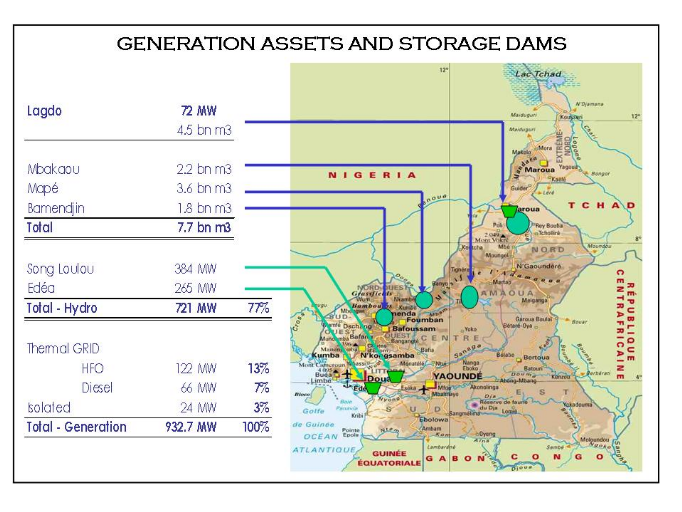
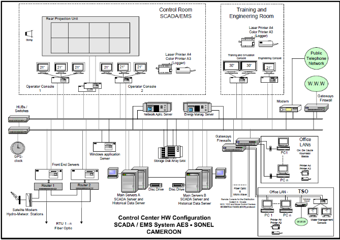
Figure 18: National
System Control Center (NSCC), Douala
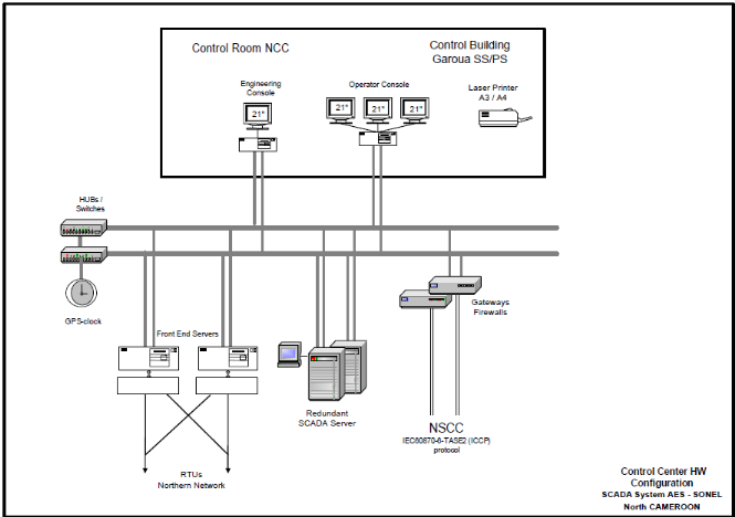
Figure 19: North
Control Center, Garoua

Figure 20:
Yaoundé Control Center, Yaoundé
 
| 

