1.3.1.3.2.2: Softwares
Apart from some excel sheets used by the hydrology department
in the analysis of hydrological data and the SCADA software, the main software
used by the network operations department is operations and capacity planning
is the QSOM (Quantitative systems for Operations Management) software. It is
used in daily dispatching through unit commitment and the establishment of a
production plan.
1.3.2: The TSO and the new
electricity market system
The process to open-up the electricity markets system in
Cameroon as stated by the new electricity law started after the privatization
of SONEL on the 18 July 2008 by the American AES Corporation. AESS would soon
share the electricity market in Cameroon with Independent Power Producers
(IPP), Independent Transmission Companies (ITCs) and independent retailers
including large customers [2].
The TSO (Transmission System Operator) presently part of the
network operations department would be unbundled from AESS and assigned to a
subsidiary of AESS as stated in the concession agreement. AESS shall conserve
transmission assets, asset owner responsibilities and exclusive rights to
provide transmission services in the scope of transmission while the TSO shall
conserve exclusive right to managing operations on the transmission network.
The TSO would be at the heart of this new electricity market
system as demonstrated in the future hierarchical dispatching structure
below
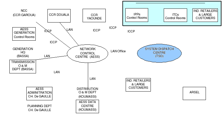
Figure 7: Future
hierarchical dispatching structure [3]
The TSO in this new electricity market structure has as
mission the following [23];
1. Maintain the security and the balance of load flows on the
Transmission system and undertake the management of network power flows, taking
account of exchanges within the interconnected network;
2. Maintain the reliability and security of the Transmission
system, taking account of constraints upon the latter, and implement such
measures as are required to ensure the availability of all the requisite
auxiliary services and the maintenance of a high level of reliability and
security on the electric system;
3. Ensure the optimum use of existing capacity;
4. Manage the take-up of available electricity production at
the lowest possible price, preferably from the national market in case of
exports, in accordance with functions in the general interest to be undertaken
by the Transmission System Operator;
5. Guarantee the availability of management data and ensure
that interested parties receive any information required for the purposes of
billing and the settlement of payments in respect of services provided;
6. Not practice any discrimination between system users,
subject to the limits of available capacity;
7. Supply to the operator of any other system which is
connected to the SONEL system sufficient information to allow the secure,
effective and coordinated operation of interconnected networks;
8. Facilitate the interconnection of systems under the terms
of agreements concluded with any other system operators, participate in the
implementation of rules governing interconnection and supervise compliance with
these rules;
9. Prepare and submit to the Agency an annual estimate of
Generating capacity, Transmission capacity and Distribution capacity connected
to the system; and
10. Identify requirements for interconnection with other
systems, potential Transmission capacity and electricity demand for the next
ten (10) years; this analysis will be updated and submitted to the Agency each
year.
In order to aid the TSO to properly execute its functions and
carry out its mission, AESS is about to put into operation a new PMS (Power
Management System) on the whole Cameroonian electricity transmission network
which also forms part of the context of this work and of which the TSO (more
specifically, the information system division under which i did my internship
and of whom this dissertation concerns) has as obligation under this context
Ø Project ownership responsibilities for the
implementation of the Power Management System (PMS) [23]
Ø Coordination of the proper operational integration of
the PMS in business processes within the AESS [23]
And of which the business integration of this PMS in line with
the PMS project opening memo is the last phase for the complete realisation of
these obligations.
1.3.3: Problem
statement
Based on the concession agreement signed between AES and the
Cameroonian government which requested [2]
1) Modernization of company equipments
2) Modernization of operations management
AESS is about to put into operation a new PMS for the
supervision, control and management of operations on the whole Cameroonian
electricity transmission network. Also in order to ensure security and
reliability in electricity network and market operations, this information
system and the information obtained would be shared between the TSO (system
operator, who has exclusive right to operations management) and AESS
(concession holder, who conserves asset owner responsibilities and has
exclusive rights to provide transmission services).
Faced with a business integration challenge which key to
correct implementation, complete technology transfer, proper operation and the
absolute ownership of this system; AESS has decided study and analyze all the
requirements and aspects for the business integration of this system in the bid
to design specifications and quality assurance measures for efficient business
integration.
In other words, it involves designing quality assurances
measures (requirements and specifications) used in the subsequent development
of a number of quality assurance checklists to ensure the efficient business
integration of this new PMS system. These quality assurance checklists to be
established subsequently would be used to demonstrate compliance with the
defined business integration requirement specifications upon completion of
business integration to ensure correct implementation; full, proper and
sustained operation; complete technology transfer and absolute ownership of
system.
1.3.4: PMS
description
The PMS is an IT-based solution package composed of SCADA
infrastructures on top of which specific softwares are implemented to manage
operations such as planning, supervisory control, energy accounting between the
main nodes of the network e.t.c. More specifically, it is an information system
with information management infrastructures/systems for real-time analysis of
information.
1.3.4.1: Compositional
overview
The new PMS system to be supplied by Siemens (EPC contractor)
and to be business integrated is made up of the following three subsystems with
their corresponding main operational objectives;
1. SCADA/EMS with main operational objective the optimization
of network monitoring and control as well as switching operations for a better
system security and reliability [2]
2. Water Resources Management System (WRMS) with main
operational objective the optimization of the water discharge from the storage
dams for an efficient energy generation and water use in the hydro power plants
[2]
3. Automatic Meter reading/Metering Management System/Energy
Data Management system (AMR/MMS/EDM) with main operational objectives the
provision of reliable metering data from any major grid node of the overall
system network to all entitled stakeholders and the determination of electrical
losses inside the electrical supply system of Cameroon [2].
The compositional overview of the PMS is depicted in the
figure below where real time data/information from the substations and power
stations, the meteo and hydro stations and grid metering points acquired and
processed by their respective hardwares; RTUs/data concentrators,
meteorological/flow meters and grid connected meters; are transported over a
telecommunications network to an interface hardware platform (made up of
servers, switches, e.t.c) to be analyzed and processed by their respective
softwares (information management systems); SCADA/EMS, EDM/MMS and WRMS
softwares.
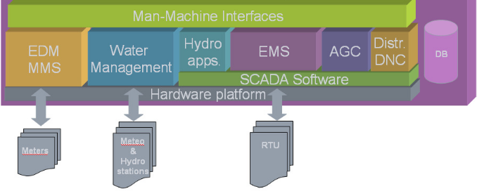
Figure 8: Compositional
overview of PMS system [5]
1.3.4.2: Technical Overview
of PMS
This IT-based solution package is made up of both hardware
(network and control) and software components. The major network and control
components of this PMS to be installed at the different substations, power
stations, hydro and meteo stations and at the system controls centres are
depicted in the figure below showing an overview of the PMS
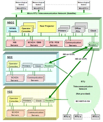
Figure 9: SCADA/PMS
system Overview [5]
All the different data acquisition stations and system control
centers have communication buildings containing all the different
telecommunication equipments such as communication back-up power supplies e.g.
UPS, diesel generator, battery e.t.c; data concentrators; switches; routers and
the fiber optic nodes e.t.c. All sensors and data acquisition equipments at the
different data acquisition stations and grid metering points are connected
through a highly redundant communication network to system control centers for
information and operations management.
All RTUs communicate with the SCADA system through dedicated
data channels. They will have single and double pole statuses, analog and pulse
accumulator inputs, as well as supervisory control outputs for switching of
circuit breakers and isolators as well as raise/lower controls for tap-changing
transformers. These RTUs communicate in [1]
Ø IEC 60870-5-101 (balanced and unbalanced mode)
Ø IEC 60870-5-104 (which is TCP/IP and thus
routable)
Ø dual-port-communication either
o With homogenous protocols (IEC 101-101 / IEC 104-104)
o Or with mixed protocols (IEC 104 main channel / IEC 101
standby channel).
Ø With a future capability of communicating in the IEC
61850
Six different telecommunication systems make up the
telecommunication network associated to this new PMS system for voice and data
transmission and include [1]
Ø OHTL (Over-Head Transmission Line) Power Line Carrier
suitable for voice, SCADA data, corporate data and hotline telephones
Ø GSM fixed mobile facility at each substation
Ø Low Power VHF (Very High Frequency) link to remote
offices
Ø Satellite link to the Garoua office in the North
Ø Microwave link
Ø FOC (Fiber Optic Cable) laid in the way leave of the
existing OHTL's
At the system control centers, functions (information
management systems and their corresponding applications) are compartmentalized
into functional blocks/subsystems with the subsystems implemented on different
servers and the servers distributed along a redundant Local Area Network (LAN).
All the information managements systems (SCADA, EMS, WRMS, MMS and EDMS) and
their corresponding application are critical in operations management and are
hence implemented on dual redundant servers, with one of the servers serving as
a hot standby. All the servers, workstations and network equipments are
interconnected through a redundant fast Ethernet LAN using Ethernet switches.
The most important and fundamental hardware equipments found in all the system
control centers include [5]
§ Application and system servers, performing all the main
data processing tasks and acting as the information reference sources for the
entire system. Critical applications are implemented on dual redundant servers
with one of the servers functioning in the hot standby mode.
§ Multiple workstation consoles with about 3 VDU per
workstation. The workstation consoles are configured for different purposes
(Operator, Engineering, Maintenance, Training e.t.c).
§ Large wall display unit connected to the real-time LAN
to rear-project any displays that would ordinarily be visualized on a
workstation
§ Redundant fast Ethernet 10/100base T switches to
interconnect the different system control center equipments
§ GPS time and Frequency System (TFS)
§ Redundant color and Black & white printers
accessible from workstation consoles for printing of the operating status of
the network anytime an event occurs.
§ Redundant WAN routers for interconnection to other
control centers and RTUs
§ Firewalls for connection to other LAN and WAN such
corporate office LAN, TSO LAN, the internet
This new PMS as depicted in the figure above would be
implemented on three system control centers with the following borders of
operational responsibility [5]
1. A National System Control Center (NSCC) to control and
monitor the entire HV network of AES SONEL in Cameroon, including the outgoing
MV feeders, located in Douala and made up of SCADA and EMS applications.
2. A regional Northern Control Center (NCC) to control and
monitor (in case of break-down of data communication to Douala) the isolated HV
network of the North, including the outgoing MV feeders, located in Garoua and
made up of only SCADA applications.
3. A back-up Yaoundé regional Control Center (YCC) to
control and monitor (in case of break-down of data communication to Douala) the
Yaoundé HV network including the outgoing MV feeders located in
Yaoundé and made up of only SCADA applications.
Also, regional distribution grid monitoring and partial
control would be done at the system control centers and by the regional
distribution control centers (CCRs) in the future.
LAN connections shall be installed between the AESS offices in
Douala (Bassa, Charles de Gaulle and Koumassi), the system control centers and
the TSO offices for information sharing on transmission and distribution
planning and maintenance by AESS as well as on other issues such as energy
dispatch, hydro-thermal scheduling/coordination and water management by the TSO
as depicted in the figure below which shows an principle overview of the PMS
and the future hierarchical dispatching system.
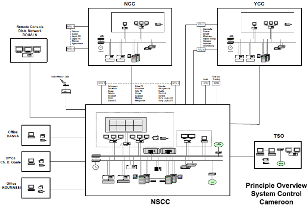
Figure 10: Principle
overview of system control center, Cameroon [1]
Also as depicted in the figure above, there will be an
operator workstation with a three screen Console for each distribution network
((Yaoundé (YCC), Garoua (NCC) and Douala (Remote
console)). For the distribution grid of Douala one operator
workstation and corresponding Console will be located in the same building as
the SNCC. The subsystems (back-up Control Centers, YCC and NCC) for
Yaoundé and Garoua will be located at the AESS building in Mbankolo and
the control building of the Garoua SS/PS. From these workstations the MV
feeders in the corresponding HV/MV substations can be remotely controlled and
supervised.
1.3.4.3: Functional
Overview of PMS
Any time there is a change of state in the network as a result
of an event, signals (alarms, status, measurements and control signals) from
the sensors and actuators locally controlling the different substation and
power station equipments, stored and processed in the RTUs/Data concentrators,
are send over a redundant telecommunications network to the control centers and
then displayed in real time on the workstation consoles of the grid dispatch
operators. This real time data and displays give the operators minute-by-minute
up-to-date information about the status of the network and are also used by the
underlying EMS application modules for real time analysis and computations to
aid them in decision-making.
In addition to some of the supervision, control, data
acquisition, data processing and MMI functions provided by the existing SCADA
system and which would be renewed and extended by the SCADA subsystem of this
new PMS system, this new SCADA subsystem brings in new functionalities such as
[2]
· Topology processor: responsible for analyzing the
open/closed status of network switching devices such as breakers and
disconnectors in order to define the configuration of the network for screen
projection and display.
· Data dissemination: provides the ability to transmit
and receive data (telemetered data, calculated and manually entered data, data
generated by application programs and text data such as alarm messages, event
messages e.t.c to and from other control centers and other computer systems e.g
enterprise management systems or enterprise wide databases, settlement systems
e.t.c.
· Outage scheduler: assist authorized user in scheduling
future outages of power system equipment.
· Information storage and retrieval functions such as
journalizing, energy data collection and calculation, disturbance data for post
mortem review.
The figure below illustrates the different functional
blocks/subsystems of the new PMS and how they interact with each other. The EMS
subsystem has the main task of economically optimizing the utilization of
generation facilities within the constraints imposed by the transmission
network and power/energy exchange contracts or power producers and includes all
the task related to energy purchase, determination of generation cost,
generation maintenance schedules, unit commitment, load frequency control e.t.c
The Energy Management Software in the Power Applications refers to the group of
functions that monitors and controls the generated and exchanged power in the
electric system. In real-time the EMS there would be a significant amount of
coordination between the control center and the various power plant facilities.
System-wide economic benefits are to be achieved when this coordination would
be optimized taking into consideration unit efficiencies, fuel costs and
availability, transmission efficiencies, unit and transmission outages as well
as interchange power availability and price.
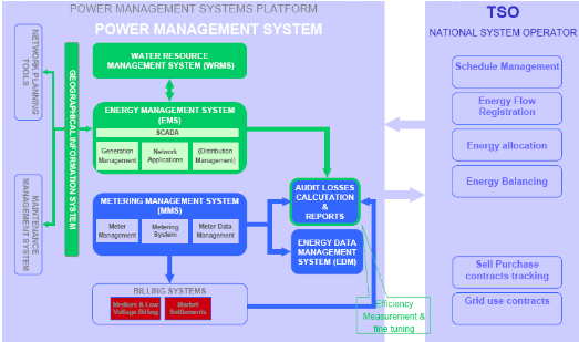
Figure 11: PMS
subsystems functions [2]
The following new functionalities amongst others would be
brought in by the new EMS subsystem in capacity and operations planning and
metering and scheduling [1];
· Load forecast: forecast on demand on daily, weekly,
monthly seasonally (rainy and dry season) and annually basis as well as use the
forecasting model predict initially stream flow between the reservoirs
(Mbakaou, Mape and Bamendjin) and the power plants (Edea and Songloulou).
· Economic dispatch: allocate generation in an optimal
manner among committed units to minimize production cost while respecting
reserve requirements and other constraints
· Load Frequency Control (LFC): to keep controlled area's
frequency, area interchange and system time within pre-defined limits.
· Interchange scheduler: allow the operator to develop
record and maintain the interchange transactions negotiated with other systems
and/or generating companies.
· Reserve monitor: to monitor and account for available
generation capacity and system reserves both system-wise and on a generating
unit basis as well as reactive power reserve to allow voltage control
regulation.
· Hydro scheduling: responsible for determining optimal
operation of the hydro system, taking into account constraints and limits.
· Hydro-thermal coordination
· Energy accounting: for calculating the cost of energy
interchanges based on tariffs defined in the respective transactions.
· Power flow: enable operator to study power flow under a
wide variety of different network situations
· Short circuit analysis: analyze potential short
circuits in network and compute fault currents at selected buses and fault
current contributions from other equipment near the faulted buses
· State estimator: application that processes raw
real-time telemetry data and pseudo measurements to provide real time power
flow solution for the entire network as well as detect and isolate failed or
bad data using either the orthogonal transformation algorithm or the normal
equation with constraint algorithm. Also checks and verifies credibility of
data including limits, consistencies and validity.
· Contingency analysis: application that analyses the
threats to the power network that can potentially result from a credible set of
contingent events under steady-state power system conditions e.g. short
circuit, line loss e.t.c using either the Newton-Raphson's or the fast
decoupled power flow algorithm.
· Optimal power flow: application that enables
optimization in the utilization of the power system generation and transmission
network by using a non-linear programming method to identify operating bottle
necks and the marginal cost of binding constraints in MW dispatch, MVAR
dispatch, fuel cost minimization and remedial scheduling.
· Dynamic stability simulation: solve power systems
dynamic problems such providing accurate simulation models and algorithms to
cover the complete range of transient and time frames, calculation of initial
conditions based on power flow results e.t.c
· Harmonic analysis: for carrying out frequency scan and
harmonic load flow for the determination of network natural frequencies and for
filter design.
· Dispatcher Training Simulator: A DTS (Dispatcher
Training Simulator) for both new and experienced dispatchers with main
functions to train new dispatchers, train dispatchers on advanced EMS
applications, train dispatchers on new EMS applications, testing new EMS
packages and post disturbance analysis.
Apart from the SCADA functions of data acquisition, monitoring
and control of hydro stations, the water management system offers the following
addition functionalities [1]
· Forecasting: water flow and water level forecast at the
different hydro stations on the Sanaga and benue rivers, stream flow between
the reservoirs (Mbakaou, Mape and Bamendjin) and the power plants (Edea and
Songloulou) and inflow into the reservoirs during the discharge and filling
periods using a forecasting model that uses measured historical data from hydro
stations and forecasted precipitated data
· Determine the optimal release of water from the
reservoirs to cover entire dry season taking into consideration the hydro plant
cascading on the river basin using a catchment model
· Scheduling of hydro and thermal plants to optmise
resources especially during critical periods such as the dry season
All energy flows into and out of the HV network and other
energy flows within the energy market would be processed by the MMS [1].
Metering data from all the metering points equipped with metering equipments
(modems/IEDs) would be send over a telecommunications network to the central
MMS. This MMS combined AMR system offers the following functionalities
· Data acquisition
· Data storage and processing
· Data validation
· Data reporting and analysis
There is in general a gap between the physical energy flow, which
can be determined by the meters installed in the electrical grid and the energy
flow determined by the rules of the electricity market. The transformation from
meter data into energy data is a crucial function and a prerequisite for the
settlement of the market interactions between the entitled market participants.
The energy data management (EDM) is a software component that transforms
metering data into energy data by processing besides the metering data also the
schedules of the forecasted data for consumption and electricity provision [1].
The EDM system offers the following functionalities using some mathematical,
programmable macro and scheduling functions with an interface to contractual
and economic information [1]
· Transformation from metering data to energy data
· Depiction of commercial transactions
· Energy allocation
· Energy balancing
o identification of deviations between forecasted consumption
schedule and real consumption
o identification between forecasted supply schedule and real
supply schedule
o allocation of balance energy
· Verification of energy supply from various sources
The figure below depicts the flow of metering data from the
metering system through the energy data management system to the billing
system
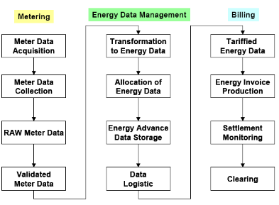
Figure 12: Metering
Management system [1]
The figure above shows clearly the function of an EDM-system
in the context of metering and billing.
1.3.5: The Business
Integration problem
Business integration involves all the processes necessary in
bringing into full and sustained operation equipments (hard and soft) in order
to make sure that they satisfy the needs they were undertaken for during
buying. While the excellent business integration of a system can have
substantial impact on the success of a business, technology alone has no value.
In the case of information systems, business integration includes all the
processes from implementation through transfer and operation to ownership and
the excellent business integration of an information system is indispensable
for
Ø Correct implementation
Ø Complete technology transfer
Ø Full, proper and sustained operation
Ø Absolute ownership
The notion of business integration of an information system
brings in the following important concepts
1. Technology transfer/technology transfer project
management
2. Project implementation/information systems project
implementation
3. Process reengineering
4. Change management
The most successful business integration implementations are
those that meet the business integration requirements and contribute to the
overall success of the business. The successful business integration of an
information system by a business is measured with metrics reflecting the key
performance indicators of the business and not IT metrics.
The socio-technical infrastructure of AESS in the case of
information systems, is made up of obsolete technologies/equipments (hard and
soft), ideas, concepts and technical as well as scientific know-how. A good
example is the LS 2000 SCADA system installed since 1990 by `Landis and Gys'
being used up to today as the main system in supervision and control while
manufacturing of its equipments/components was discontinued since 1999 making
maintenance, upgrade and extension of the system extremely difficult. New
information system technologies/equipments destined for use in operations
management such as for supervision and control, operations planning have faced
serious business integration problems because of this technical, cultural and
conceptual resistance like in the case of the new SKAN4 SCADA system supplied
by Siemens with the aim of renewing and extending the capabilities of the LS
2000 SCADA system as a result of network expansion and increase in the number
of substations, which is not fully operated and has been partially abandoned;
the new daily dispatching software (QSOM) which faced resistance in application
by the dispatch operators e.t.c. This obsolete socio-technical infrastructure
and the concept of routine makes it extremely difficult for AESS to adapt and
change against the reception of new equipments/technology which would impact
the technological, functional and organization aspects of the company.
| 

