Chapitre 2 : Phase de mise en oeuvre
I. Scenario Configurations serveur DHCP et poste
clients
I.1. Configuration postes clients
Nous procédons à la configuration de toutes les
cartes réseaux du parc informatique en authentification 802.1.
I.2. définition des plages d'adresses des
VLANs
Le serveur DHCP est sous Windows 2003 serveur, nous
définissons 6 étendues comme suit :
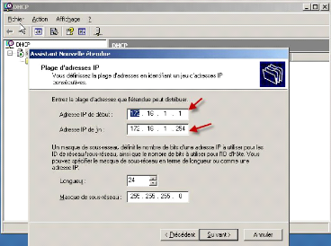
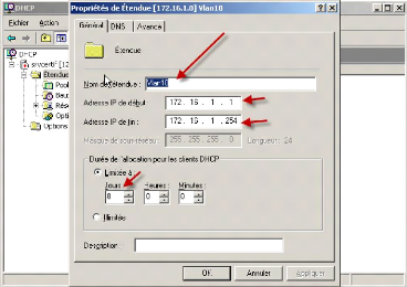
· Etendue Vlan10 attribuant la plage [172.16.1.1 à
172.16.1.254]
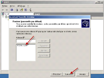
· IP passerelle Vlan10 [172.16.1.254]
· Etendue Vlan20 attribuant la plage [172.16.2.1 à
172.16.2.254]
· IP passerelle Vlan20 [172.16.2.254]
· Etendue Vlan30 attribuant la plage [172.16.3.1 à
172.16.3.254]
· IP passerelle Vlan30 [172.16.3.254]
· Etendue Vlan40 attribuant la plage [172.16.4.1 à
172.16.4.254]
· IP passerelle Vlan40 [172.16.4.254]
· Etendue Vlan50 attribuant la plage [172.16.5.1 à
172.16.5.254]
· IP passerelle Vlan50 [172.16.5.254]
· Etendue Vlan60 attribuant la plage [172.16.6.0 à
172.16.6.255]
· IP passerelle Vlan60 [172.16.6.254]
NB : toutes les adresses IP des serveurs
sont fixées.
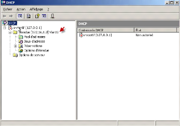
I.3. Configuration des étendues des
VLANs
1. Lancez la console DHCP, propriété sur
l'étendue existant
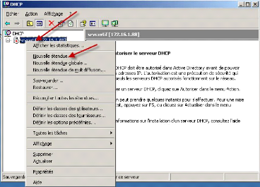
2. Sélectionner nouvelle étendue
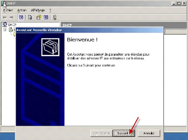
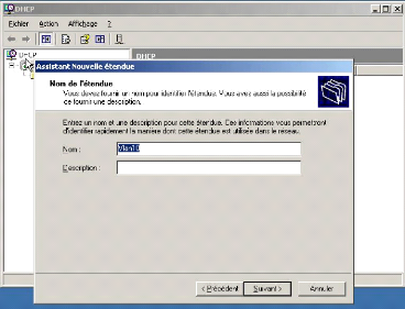
3. Nommage du Vlan
4. Plage d'adresse du vlan
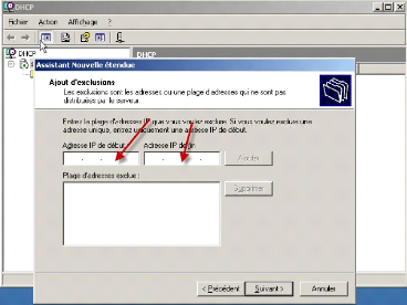
5. La plage d'exclusion. Pour l'instant nous n'avions pas
prévu de plage d'adresse.
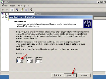
6. Durée du bail
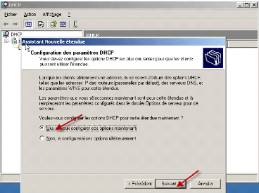
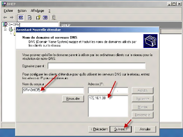
7. Configuration des options
8. La passerelle par défaut
9. DNS et adresse IP serveur
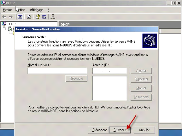
10. Le serveur Win, nous n'avions pas prévu de d'adresse
pour le Win
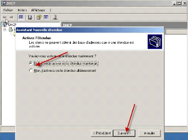
11. Activation de l'étendue
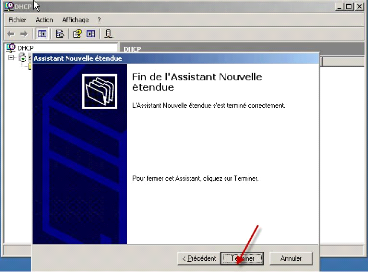
12. Fin de la configuration de l'étendue
13. vérification et activation de l'étendue
14. Propriété de l'étendue du Vlan 10
NB : pour la configuration des VLANs 20,
30, 40, 50, 60 nous procéderons de la même manière que le
VLAN 10, ce qui donne ceci :
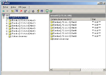
Voici notre serveur DHCP qui est configuré et prêt
à distribuer des adresses, lorsque la configuration des Switchs sera
terminée.
I. Etapes des scenarios de déploiement des
VLANs
I.1. Création des liens Trunk 802.1q
Il est important pour nous de créer un trunk entre les
différents
SWITCHS. C'est en effet par celui-ci que les trames
étiquetées transitent. Pour la mise en place de ce lien, nous
avions utilisé des câbles croisés. Ce lien trunk physique
va regrouper plusieurs connexions logiques.
Manipulation1 :
|
Switch>en
Switch#config t
Enter configuration commands, one per line. End with CNTL/Z.
Switch(config)#host
Switch(config)#hostname SWITCH1
SWITCH1(config)#int
SWITCH1(config)#interface fas
SWITCH1(config)#interface fastEthernet 0/3
SWITCH1(config-if)#sw
SWITCH1(config-if)#switchport mode trunk
%LINEPROTO-5-UPDOWN: Line protocol on Interface
FastEthernet0/3, changed state to down
%LINEPROTO-5-UPDOWN: Line protocol on Interface
FastEthernet0/3, changed state to up
SWITCH1(config)#int
SWITCH1(config)#interface fa
SWITCH1(config)#interface fastEthernet 0/4
SWITCH1(config-if)#sw
SWITCH1(config-if)#switchport mode trunk
%LINEPROTO-5-UPDOWN: Line protocol on Interface
FastEthernet0/4, changed state to down
|
%LINEPROTO-5-UPDOWN: Line protocol on Interface
FastEthernet0/4, changed state to up
SWITCH1(config-if)#exit
SWITCH1(config)#int
SWITCH1(config)#interface fas
SWITCH1(config)#interface fastEthernet 0/5
SWITCH1(config-if)#sw
SWITCH1(config-if)#switchport mode trunk
%LINEPROTO-5-UPDOWN: Line protocol on Interface
FastEthernet0/5, changed state to down
%LINEPROTO-5-UPDOWN: Line protocol on Interface
FastEthernet0/5, changed state to up
SWITCH1(config-if)#sw
SWITCH1(config-if)#switchport mode trunk
SWITCH1(config-if)#exit
SWITCH1(config)#exit
%SYS-5-CONFIG_I: Configured from console by console
Manipulation2 :
SWITCH1#sh
SWITCH1#show int
SWITCH1#show interfaces trunk
|
Port
|
Mode
|
Encapsulation Status
|
Native vlan
|
|
Fa0/2
|
on
|
802.1q
|
trunking
|
1
|
|
Fa0/3
|
on
|
802.1q
|
trunking
|
1
|
|
Fa0/4
|
on
|
802.1q
|
trunking
|
1
|
|
Fa0/5
|
on
|
802.1q
|
trunking
|
1
|
|
Port
|
Vlans allowed on trunk
|
|
|
Fa0/2
|
1-1005
|
|
|
|
|
Fa0/3
|
1-1005
|
|
|
|
|
Fa0/4
|
1-1005
|
|
|
|
|
Fa0/5
|
1-1005
|
|
|
|
|
Port
|
Vlans allowed and active in management domain
|
|
Fa0/2
|
1,10,20,30,40,1002,1003,1004,1005
|
|
Fa0/3
|
1,10,20,30,40,1002,1003,1004,1005
|
|
Fa0/4
|
1,10,20,30,40,1002,1003,1004,1005
|
|
Fa0/5
|
1,10,20,30,40,1002,1003,1004,1005
|
|
Port
|
Vlans in spanning tree forwarding state and not
pruned
|
|
Fa0/2
|
1,10,20,30,40,1002,1003,1004,1005
|
|
Fa0/3
|
1,10,20,30,40,1002,1003,1004,1005
|
|
Fa0/4
|
1,10,20,30,40,1002,1003,1004,1005
|
|
Fa0/5
|
1,10,20,30,40,1002,1003,1004,1005
|
SWITCH1#
I.2. Configuration du Spanning-tree
Spanning-Tree va répondre à la
problématique de redondance de boucle dans le réseau. La
présence de boucle génère des tempêtes de diffusion
(broadcast en anglais) qui paralysent le réseau
|
SWITCH1#sh
SWITCH1#show span
SWITCH1#show spanning-tree VLAN0001
Spanning tree enabled protocol ieee Root ID Priority
32769
Address 0001.6449.C0D7
|
Cost 19
Port 5(FastEthernet0/5)
Hello Time 2 sec Max Age 20 sec Forward Delay 15 sec
Bridge ID Priority 32769 (priority 32768 sys-id-ext 1)
Address 00D0.9702.2B08
Hello Time 2 sec Max Age 20 sec Forward Delay 15 sec Aging
Time 20
|
Interface
|
Role Sts Cost
|
Prio.Nbr Type
|
|
Fa0/2
|
Desg FWD 19
|
128.2
|
Shr
|
|
Fa0/3
|
Desg FWD 19
|
128.3
|
P2p
|
|
Fa0/4
|
Desg FWD 19
|
128.4
|
P2p
|
|
Fa0/5
|
Root FWD 19
|
128.5
|
P2p
|
|
VLAN0010
|
|
|
|
Spanning tree enabled protocol ieee
Root ID Priority 32778
Address 00D0.9702.2B08
This bridge is the root
Hello Time 2 sec Max Age 20 sec Forward Delay 15 sec
Bridge ID Priority 32778 (priority 32768 sys-id-ext 10)
Address 00D0.9702.2B08
Hello Time 2 sec Max Age 20 sec Forward Delay 15 sec Aging
Time 20
|
Interface
|
Role Sts Cost
|
Prio.Nbr Type
|
|
Fa0/2
|
Desg FWD 19
|
128.2
|
Shr
|
|
Fa0/3
|
Desg FWD 19
|
128.3
|
P2p
|
|
Fa0/4
|
Desg FWD 19
|
128.4
|
P2p
|
|
Fa0/5
|
Desg FWD 19
|
128.5
|
P2p
|
|
VLAN0020
|
|
|
|
Spanning tree enabled protocol ieee Root ID Priority
32788
Address 0001.6449.C0D7
Cost 19
Port 5(FastEthernet0/5)
Hello Time 2 sec Max Age 20 sec Forward Delay 15 sec
Bridge ID Priority 32788 (priority 32768 sys-id-ext 20)
Address 00D0.9702.2B08
Hello Time 2 sec Max Age 20 sec Forward Delay 15 sec Aging
Time 20
Interface Role Sts Cost Prio.Nbr Type
Fa0/2 Desg FWD 19 128.2 Shr
Fa0/3 Desg FWD 19 128.3 P2p
Fa0/4 Desg FWD 19 128.4 P2p
Fa0/5 Root FWD 19 128.5 P2p
VLAN0030
Spanning tree enabled protocol ieee
Root ID Priority 32798
Address 00D0.9702.2B08
This bridge is the root
Hello Time 2 sec Max Age 20 sec Forward Delay 15 sec
Bridge ID Priority 32798 (priority 32768 sys-id-ext 30)
Address 00D0.9702.2B08
Hello Time 2 sec Max Age 20 sec Forward Delay 15 sec Aging
Time 20
|
Interface
|
Role Sts Cost
|
Prio.Nbr Type
|
|
Fa0/2
|
Desg FWD 19
|
128.2
|
Shr
|
|
Fa0/3
|
Desg FWD 19
|
128.3
|
P2p
|
|
Fa0/4
|
Desg FWD 19
|
128.4
|
P2p
|
|
Fa0/5
|
Desg FWD 19
|
128.5
|
P2p
|
|
VLAN0040
|
|
|
|
Spanning tree enabled protocol ieee
Root ID Priority 32808
Address 00D0.9702.2B08
This bridge is the root
Hello Time 2 sec Max Age 20 sec Forward Delay 15 sec
|
Bridge ID Priority 32808 (priority 32768 sys-id-ext 40)
Address 00D0.9702.2B08
Hello Time 2 sec Max Age 20 sec Forward Delay 15 sec Aging
Time 20
Interface Role Sts Cost Prio.Nbr Type
Fa0/2 Desg FWD 19 128.2 Shr
Fa0/3 Desg FWD 19 128.3 P2p
Fa0/4 Desg FWD 19 128.4 P2p
Fa0/5 Desg FWD 19 128.5 P2p
|
I.3. Configuration VTP Server/Client
Manipulation1 : mode serveur
|
SWITCH1>en
SWITCH1#config t
Enter configuration commands, one per line. End with CNTL/Z.
SWITCH1(config)#ena
SWITCH1(config)#enable password inova
SWITCH1(config)#vtp domain INOVA
Changing VTP domain name from NULL to INOVA
SWITCH1(config)#vtp password inova
Setting device VLAN database password to inova
SWITCH1(config)#exit
|
Vérification du domaine
serveur:
|
SWITCH1#show vtp st
SWITCH1#show vtp status VTP Version : 2
Configuration Revision : 0
|
Maximum VLANs supported locally : 255
Number of existing VLANs : 5
VTP Operating Mode : Server
VTP Domain Name : INOVA
VTP Pruning Mode : Disabled
VTP V2 Mode : Disabled
VTP Traps Generation : Disabled
MD5 digest : 0xCB 0xBC 0x5D 0x4B 0x7A 0x4F 0x04 0x3A
Configuration last modified by 0.0.0.0 at 0-0-00
00:00:00
Local updater ID is 0.0.0.0 (no valid interface
found)
Manipulation 2 : mode client
|
SWITCH2>en
SWITCH2#config t
Enter configuration commands, one per line. End with CNTL/Z.
SWITCH2(config)#vtp mode client
Setting device to VTP CLIENT mode.
SWITCH2(config)#vtp domain INOVA
Domain name already set to INOVA.
SWITCH2(config)#vtp password inova
Setting device VLAN database password to inova
SWITCH2(config)#exit
%SYS-5-CONFIG_I: Configured from console by console
|
NB : Cette manipulation est
répétée sur le Switch 2 et 3
Vérification du domaine
client:
|
SWITCH2>en
SWITCH2#sh
SWITCH2#show vtp status
VTP Version : 2
Configuration Revision : 4
Maximum VLANs supported locally : 255 Number of existing
VLANs : 9
VTP Operating Mode : Client
VTP Domain Name : INOVA
VTP Pruning Mode : Disabled
VTP V2 Mode : Disabled
|
VTP Traps Generation : Disabled
MD5 digest : 0xBF 0x21 0x85 0x3F 0x3E 0x 0xE9 0x69
Configuration last modified by 0.0.0.0 at 3-1-93
07:20:44

10 SERVEUR active
20 ADMINISTRATION active
60 DIRTECH active
1002 fddi-default active
1003 token-ring-default active
1004 fddinet-default active
1005 trnet-default active
SWITCH1>en Password:
SWITCH1#vl
SWITCH1#vlan da SWITCH1#vlan database
SWITCH1(vlan)#vlan 10 name SERVEUR
VLAN 10 added: Name: SERVEUR
SWITCH1(vlan)#vlan 20 name ADMINISTRATION VLAN 20
added:
Name: ADMINISTRATION SWITCH1(vlan)#vlan 60 name
DIRTECH
VLAN 60 added: Name: DIRTECH
SWITCH1(vlan)#exit
APPLY completed. Exiting....
SWITCH1#sh
SWITCH1#show vlan
1 default active Fa0/1, Fa0/2, Fa0/6, Fa0/7
Fa0/8, Fa0/9, Fa0/10, Fa0/11 Fa0/12, Fa0/13, Fa0/14, Fa0/15
Fa0/16, Fa0/17, Fa0/18, Fa0/19 Fa0/20, Fa0/21, Fa0/22, Fa0/23 Fa0/24, Gig1/1,
Gig1/2
VLAN Name Status Ports
I.4. Configuration de la base de données VLAN
Manipulation 1 :

1 enet 100001 1500 - - - - - 0 0
10 enet 100010 1500 - - - - - 0 0
--More--
SWITCH2>en
SWITCH2#config t
Enter configuration commands, one per line. End with
CNTL/Z.
SWITCH2(config)#exit
%SYS-5-CONFIG_I: Configured from console by console
SWITCH2#vl
SWITCH2#vlan da
SWITCH2#vlan database
SWITCH2(vlan)#vlan 10 name SERVEUR
VLAN 10 added:
Name: SERVEUR
SWITCH2(vlan)#vlan 20 name ADMINISTRATION
VLAN 20 added:
Name: ADMINISTRATION
SWITCH2(vlan)#vlan 30 name GESABEL
VLAN 30 added:
Name: GESABEL
SWITCH2(vlan)#vlan 40 name OCEANGALATEE
VLAN 40 added:
Name: OCEANGALATEE
SWITCH2(vlan)#exit
APPLY completed.
Exiting....
SWITCH2#sh
SWITCH2#show vlan
10 SERVEUR active
20 ADMINISTRATION active
30 GESABEL active
40 OCEANGALATEE active
1002 fddi-default active
1003 token-ring-default active
1004 fddinet-default active
1005 trnet-default active
1 default active Fa0/2, Fa0/3, Fa0/4, Fa0/5
Fa0/6, Fa0/7, Fa0/8, Fa0/9 Fa0/10, Fa0/11, Fa0/12, Fa0/13
Fa0/14, Fa0/15, Fa0/16, Fa0/17 Fa0/18, Fa0/19, Fa0/20, Fa0/21 Fa0/22, Fa0/23,
Fa0/24
VLAN Name Status Ports
VLAN Type SAID MTU Parent RingNo BridgeNo Stp BrdgMode Trans1
Trans2

SWITCH3>en SWITCH3#vlan database
SWITCH3(vlan)#vlan 30 name GESABEL
VLAN 30 added:
Name: GESABEL
SWITCH3(vlan)#vlan 40 name OCEANGALATEE VLAN 40
added:
Name: OCEANGALATEE SWITCH3(vlan)#vlan 50 name NEWSTECH VLAN
50 added:
Name: NEWSTECH
SWITCH3(vlan)#EXIT
APPLY completed. Exiting....
SWITCH3#sh
SWITCH3#show vlan
30 GESABEL active
40 OCEANGALATEE active
50 NEWSTECH active
1002 fddi-default active
1003 token-ring-default active
1004 fddinet-default active
1005 trnet-default active
1 enet 100001 1500 - - - - - 0 0
30 enet 100030 1500 - - - - - 0 0
40 enet 100040 1500 - - - - - 0 0
1 default active Fa0/2, Fa0/3, Fa0/4, Fa0/5
Fa0/6, Fa0/7, Fa0/8, Fa0/9 Fa0/10, Fa0/11, Fa0/12, Fa0/13
Fa0/14, Fa0/15, Fa0/16, Fa0/17 Fa0/18, Fa0/19, Fa0/20, Fa0/21 Fa0/22, Fa0/23,
Fa0/24
VLAN Name Status Ports
VLAN Type SAID MTU Parent RingNo BridgeNo Stp BrdgMode Trans1
Trans2
|
Switch>en
Switch#vlan database
Switch(vlan)#vlan 20 name ADMINISTRATION
VLAN 20 added:
Name: ADMINISTRATION
Switch(vlan)#vlan 50 name NEWSTECH
VLAN 50 added: Name: NEWSTECH
Switch(vlan)#vlan 60 name DIRTECH
VLAN 60 added: Name: DIRTECH
Switch(vlan)#vlan 70 name WIFI
VLAN 70 added:
Name: WIFI Switch(vlan)#EXIT APPLY completed.
Exiting....
Switch#sh
Switch#show vlan
VLAN Name Status Ports
1 default active Fa0/2, Fa0/3, Fa0/4, Fa0/5
Fa0/6, Fa0/7, Fa0/8, Fa0/9 Fa0/10, Fa0/11, Fa0/12, Fa0/13
Fa0/14, Fa0/15, Fa0/16, Fa0/17 Fa0/18, Fa0/19, Fa0/20, Fa0/21 Fa0/22, Fa0/23,
Fa0/24
20 ADMINISTRATION active
50 NEWSTECH active
60 DIRTECH active
70 WIFI active
1002 fddi-default active
1003 token-ring-default active
1004 fddinet-default active
1005 trnet-default active
|
I.5. Configuration des ports attribués aux VLAN
Manipulation :

SWITCH1>en
Password:
SWITCH1#config t
Enter configuration commands, one per line. End with
CNTL/Z.
SWITCH1(config)#int
SWITCH1(config)#interface range fas
SWITCH1(config)#interface range fastEthernet 0/6 - 12
SWITCH1(config-if-range)#sw
SWITCH1(config-if-range)#switchport access vlan 10
SWITCH1(config-if-range)#exit
SWITCH1(config)#in
SWITCH1(config)#interface fas
SWITCH1(config)#interface range fastEthernet 0/18 - 21
SWITCH1(config-if-range)#sw
SWITCH1(config-if-range)#switchport access vlan 20
SWITCH1(config-if-range)#exit
SWITCH1(config)#int
SWITCH1(config)#interface range fas
SWITCH1(config)#interface range fastEthernet 0/13 - 17
SWITCH1(config-if-range)#sw
SWITCH1(config-if-range)#switchport access vlan 60
SWITCH1(config-if-range)#exit
SWITCH1(config)#exit
Vérification des ports attribuée
:
|
SWITCH1#show vlan
VLAN Name Status Ports
1 default active Fa0/1, Fa0/2, Fa0/22, Fa0/23
Fa0/24, Gig1/1, Gig1/2
10 SERVEUR active Fa0/6, Fa0/7, Fa0/8,
Fa0/9
Fa0/10, Fa0/11, Fa0/12
20 ADMINISTRATION active Fa0/18, Fa0/19, Fa0/20,
Fa0/21 60 DIRTECH active Fa0/13, Fa0/14, Fa0/15, Fa0/16
Fa0/17
1002 fddi-default active
1003 token-ring-default active
1004 fddinet-default active
|
NB : cette manipulation est
exécutée pareillement sur les SWITCH 1, 2 et 3
I.6. Configuration des adresses IP des VLANs
Manipulation :
SWITCH1>en
Password:
SWITCH1#conf t
Enter configuration commands, one per line. End with CNTL/Z.
SWITCH1(config)#int
SWITCH1(config)#interface vlan 10
%LINK-5-CHANGED: Interface Vlan10, changed state to
up
%LINEPROTO-5-UPDOWN: Line protocol on Interface Vlan10,
changed state to upSWITCH1(config-if)#ip address 172.16.1.10
255.255.255.0
SWITCH1(config-if)#exit
SWITCH1(config)#
SWITCH1(config)#interface vlan 20
%LINK-5-CHANGED: Interface Vlan20, changed state to
up
%LINEPROTO-5-UPDOWN: Line protocol on Interface Vlan20,
changed state to upSWITCH1(config-if)#ip address 172.16.2.20
255.255.255.0
SWITCH1(config-if)#exit
SWITCH1(config)#interface vlan 30
%LINK-5-CHANGED: Interface Vlan30, changed state to
up
SWITCH1(config-if)#ip address 172.16.3.30
255.255.255.0
SWITCH1(config-if)#exit SWITCH1(config)#int
SWITCH1(config)#interface vlan 40
%LINK-5-CHANGED: Interface Vlan40, changed state to
up
%LINEPROTO-5-UPDOWN: Line protocol on Interface Vlan40,
changed state to
upSWITCH1(config-if)#ip address 172.16.4.40
255.255.255.0 SWITCH1(config-if)#exit
SWITCH1(config)#int
SWITCH1(config)#interface vlan 50
%LINK-5-CHANGED: Interface Vlan50, changed state to
up
%LINEPROTO-5-UPDOWN: Line protocol on Interface Vlan50,
changed state to SWITCH1(config-if)#ip address 172.16.5.50
255.255.255.0
SWITCH1(config-if)#exit
SWITCH1(config)#int
SWITCH1(config)#interface vlan 60
SWITCH1(config-if)#ip address 172.16.6.60
255.255.255.0 SWITCH1(config-if)#exit
SWITCH1(config)#exit
%SYS-5-CONFIG_I: Configured from console by console
SWITCH1#
I.7. Création des pools DHCP Manipulation
1 : le pool d'adresse Vlan 10
|
Router>en
Router#conf t
Enter configuration commands, one per line. End with
CNTL/Z.
Router(config)#ip dhcp pool VLAN 10
Router(dhcp-config)#network 172.16.1.1 255.255.254.0
Router(dhcp-config)#defau Router(dhcp-config)#default-router
172.16.1.10
Router(dhcp-config)#dn Router(dhcp-config)#dns-server
172.16.1.5
Router(dhcp-config)#EXIT Router(config)#EXIT
%SYS-5-CONFIG_I: Configured from console by console
Router#
|
Manipulation 2 : le pool d'adresse Vlan 20
|
Router>en
Router#conf t
Enter configuration commands, one per line. End with CNTL/Z.
Router(config)#ip dhcp pool VLAN 20
Router(dhcp-config)#network 172.16.2.1 255.255.254.0
Router(dhcp-config)#defau
Router(dhcp-config)#default-router 172.16.2.20
Router(dhcp-config)#dn
Router(dhcp-config)#dns-server 172.16.2.5
|
|
Router(dhcp-config)#EXIT
Router(config)#EXIT
%SYS-5-CONFIG_I: Configured from console by console
Router#
|
Manipulation 3 : le pool d'adresse Vlan 30
|
Router>en
Router#conf t
Enter configuration commands, one per line. End with
CNTL/Z.
Router(config)#ip dhcp pool VLAN 30
Router(dhcp-config)#network 172.16.3.1 255.255.254.0
Router(dhcp-config)#defau Router(dhcp-config)#default-router
172.16.3.30
Router(dhcp-config)#dn Router(dhcp-config)#dns-server
172.16.3.5
Router(dhcp-config)#EXIT Router(config)#EXIT
%SYS-5-CONFIG_I: Configured from console by console
Router#
|
Manipulation 4 : le pool d'adresse Vlan 40
Router>en
Router#conf t
Enter configuration commands, one per line. End with
CNTL/Z.
|
Router(config)#ip dhcp pool VLAN 40
Router(dhcp-config)#network 172.16.4.1 255.255.254.0
Router(dhcp-config)#defau Router(dhcp-config)#default-router
172.16.4.40
Router(dhcp-config)#dn Router(dhcp-config)#dns-server
172.16.4.5
Router(dhcp-config)#EXIT Router(config)#EXIT
%SYS-5-CONFIG_I: Configured from console by console
Router#
|
Manipulation 5 : le pool d'adresse Vlan 50
|
Router>en
Router#conf t
Enter configuration commands, one per line. End with
CNTL/Z.
Router(config)#ip dhcp pool VLAN 50
Router(dhcp-config)#network 172.16.5.1 255.255.254.0
Router(dhcp-config)#defau Router(dhcp-config)#default-router
172.16.5.50
Router(dhcp-config)#dn Router(dhcp-config)#dns-server
172.16.5.5
Router(dhcp-config)#EXIT Router(config)#EXIT
%SYS-5-CONFIG_I: Configured from console by console
Router#
|
Manipulation 6 : le pool d'adresse Vlan 60
|
Router>en
Router#conf t
Enter configuration commands, one per line. End with
CNTL/Z.
Router(config)#ip dhcp pool VLAN 60
Router(dhcp-config)#network 172.16.6.1 255.255.254.0
Router(dhcp-config)#defau Router(dhcp-config)#default-router
172.16.6.60
Router(dhcp-config)#dn Router(dhcp-config)#dns-server
172.16.6.5
Router(dhcp-config)#EXIT Router(config)#EXIT
%SYS-5-CONFIG_I: Configured from console by console
Router#
|
I.8 Test de fonctionnement
Le basculement de la nouvelle infrastructure en environnement de
production, nécessite des tests de fonctionnement sur l'ensemble du
réseau.
· Vérification des différentes adresses IP
par service Vlan.
Tous les PCs des différents VLANs se voient attribuer des
adresses IP de leur serveur DNS et passerelle.
· Test de communication dans un Vlan Test concluant, les
PCs communiquent
· Test de communication entre les VLANs
Test concluant, les Pcs des différents VLANs communique
avec le Vlan 1 (Vlan SERVEUR)
· Test de fiabilité du réseau
Test concluant car, accès facile aux serveurs des bases de
données, réseau fluide
L'équipe support technique apprécie
désormais cette manière d'administrer son réseau local par
une interface web.
| 

