|

BONAFIDE CERTIFICATE
I certify that the project report titled «THE
IMPACT OF FIBER OPTIC TRANSMISSION IN MULTISERVICE NETWORK IN
RWANDA» Case Study NUR Fiber Optic Network is the bonafide work
done by Mr. NIYITEGEKA Théogène (Ug10105802) In a partial
fulfillment of the requirements for the award of Bachelor?s degree in
Electronics and Communication System Engineering and I certify that to the best
of my knowledge the work reported is my own work and it has not been submitted
anywhere for the award of any Degree.
Signature of Supervisor Signature of H.O.D
Dr. TWIZERE Celestin Eng. MANIRAGABA Ezechiel (Msc)
Signature of Internal Guide Signature of External Guide
Submitted for University examination held in October/ 2011 at
National University of Rwanda, University Avenue 117, Butare,
Rwanda.

ABSTRACT
Fiber Optic is a flexible and transparent fiber made of very
pure glass not much bigger than a human hair that acts as light pipe to
transmit light between the two ends of the fiber. In this project, we assess
the Network of National University of Rwanda and the impact of the fiber optic
in this network. The fiber optics, as seen in our project have changed the
daily life of many workers in this university throughout the high bandwidth
available with fiber optic connectivity.
We have seen that the company?s provider of network in Rwanda
can implement fiber optic in order to deliver a reliable service to their
customer.
However the bandwidth of fiber optic is usually greater than
other media cables and depending on the properties of a pure glass of the core
which make easy the total internal reflection of light inside the core and the
cladding of the fiber. The fiber optic grounded wire are allowed to transfer
more data and does not radiate electromagnetic wave in space.

DEDICATION
To The Almighty GOD
To My mother NTABUGI JEANNINE
To My
Brothers and Sisters
This project is dedicated
ACKNOWLEDGEMENT
I owe much thanks to the almighty God for his help and guidance
may this simple word express my respect to him.
I would also like to express my appreciation to Dr. Celestin
TWIZERE for his tireless efforts to guide us and supervise my work and make it
a success through encouragement and advices.
I am very grateful to my mother NTABUGI JEANNINE for her kindly
moral and financially support.
With respect, I express my special thanks to lectures and
staffs members of the faculty of Applied Sciences at National University of
Rwanda; My sincere thanks go also to Mr. NDUSHABANDI JEAN BOSCO for his
collaborating efforts to provide needed information to the achievement of this
project.
I wish to extend my sincere gratitude thanks to all classmates
and relatives who have directly or indirectly helped me and rendered great
moral encouragement.
NIYITEGEKA THEOGENE

TABLE OF CONTENTS
Bonafide certificate i
Abstract ii
Dedication iii
Acknowledgement iv
Table of contents v
List of figures viii
List of symbols ix
CHAPTER ONE: GENERAL INTRODUCTION 1
1.1 Background 1
1.2 Problem statement 2
1.3 Interest and relevance of the choice of the topic 2
1.4 Research hypothesis 3
1.5. Research methods 3
1.6 Limitation of the topic 3
1.7 Structure of the work 3
CHAPTER TWO: FIBER OPTIC TRANSMISSION 4
2.1 General information on the transmission media 4
2.1.1 Common characteristics 4
2.1.1.1 Bandwidth 4
2.1.1.2 Impedance characteristics 4
2.1.2 Guided media 5
2.1.2.1 The twister pair 5
2.1.2.2 Coaxial cable 5
2.1.2.3 Waveguide 6
2.1.2.4. Fiber optic 7
2.1.3 Unguided media 8
2.1.3.1 Microwave link 8
2.1.3.2 Satellite 8
2.2 Optical fiber cable 9
2.2.1 Definition 9
2.2.2 Principle of optical transmission. 10
2.2.4 Emission 13
2.2.5 Reception 14
2.2.6 Types of fiber optic 15
2.2.6.1 Single mode fiber optic 15
2.2.6.2 Multimode step index fiber optic 16
2.2.6.3 Multimode graded index fiber optic 17
2.2.7 Advantages and disadvantages of optical transmission 18
2.2.7.1 The advantages 18
2.2.7.2 The disadvantages 18
2.2.8 Application of fiber optic 18
2.2.9 Fiber optic connection 19
2.2.10 The principle structure of fiber optic 19
2.2.10.1. Fiber optical multiplexing 19
2.2.10.2 Fiber optical modulation 20
2.2.11 Maintenance of an optical link. 20
CHAPTER THREE: THE ANALYSIS OF FIBER OPTIC NETWORK IN NUR 21
3.1 Introduction 21
3.2 The fiber optic link 21
3.3 Passive optical network. 23
3.3.1 Ethernet passsive optic network 24
3.3.2 Broadband passive optic network 26
3.4 Active optical network 27
3.5 Sonet technology 28
3.6 Fiber optic losses 29
3.6.1 Types of losses 29
3.6.1.2 Absorption loss 30
3.6.1.3 Rayleigh scatter 31
3.6.1.4 Bending loss 31
3.6.1.5 Insertion loss 32
3.6.1.6 Return loss 32
CHAPTER FOUR: DISCUSSION AND INTERPRETATION OF THE RESULTS 33
4.1 Discussion of the network in nur 33
4.2 Fiber optic results in bandwidth and years in nur network
34
4.3 The increase in bandwidth chart of nur internet 35
4.4 The traffic monitoring of nur internet link 36
Conclusion and Recommendations 37
References 39

LISTS OF FIGURES
Figure 1: Coaxial cable 6
Figure 2: Fiber optic 7
Figure 3 : Basic structure of an optical fiber 9
Figure 4 : Principle of optical transmission 10
Figure 5 :Total internal reflection 11
Figure 6 : Emission block of fiber optical signal and laser
diodes as the source 13
Figure 7 : Block scheme of fiber optic receiver 14
Figure 8 : Single mode fiber optic 16
Figure 9 : Multimode step index fiber optic 16
Figure 10: Acceptance cone and acceptance angle in an optic fiber
17
Figure 11: Multimode graded index fiber optic 17
Figure 12 : Fiber optic multiplexing (WDM Point to Point). 19
Figure 13 : Basic Optical System 22
Figure 14 : General structure of a PON 23
Figure 15 : Downstream Traffic Flow in an Ethernet PON 25
Figure 16 : Upstream Traffic Flow in an Ethernet PON 26
Figure 17 : Active optical network 28
Figure 18 : Absorption loss 30
Figure 19 : Rayleigh Scatter loss, 31
Figure 20 : Bending loss 31
Figure 21 : Uplink bandwidth connectivity assigned to NUR 35
Figure 22 : Downlink bandwidth connectivity assigned to NUR 35
Figure 23 : The traffic internet link 36
LIST OF SYMBOLS
A/N: Analogue to Digital AON:
Active Optical Network
BPON: Broadband Passive Optical Network
CATV: Cable Television DMUX:
Demultiplexing DWDM: Dense Wavelength Division Multiplexing
EMI: Electromagnetic Interference
EPON: Ethernet Passive Optical Network
FTTB: Fiber To The Building
FTTC: Fiber To The Cabinet GPON :Gigabyte
Passive Optical Network
GPS :Global Positioning System
HDTV: High Definition Television
ICT: Information and Communication Technology
ISP: Internet Service Provider
LASER : Light Amplification by Stimulated
Emission Radiation LED: Light Emitting Diode
MTN: Mobile Telephone Network
MUX: Multiplexing
NA: Numerical Aperture
NT: Network Terminal
NUR: National University of Rwanda
OA: Optical Amplifier
ODN: Optical Distribution Network
OLT: Optical Line Terminal
ONT: Optical Network Terminal
ONU: Optical Network Unit
PON: Passive Optical Network
RCV: Receiver
RDB: Rwanda Development Board
SONET: Synchronous Optical Networking
STC: Standard Telephone and Cable
STP: Shield Twisted Pair
TDMA: Time Division Multiple Access
TRM: Transmitter
TV: Television
UTP: Unshielded Twisted Pair
VLAN: Virtual Local Access Network VSAT: Very
Small Aperture Terminal WDM: Wave Division Multiplexing
CHAPTER ONE: GENERAL INTRODUCTION
1.1 BACKGROUND
An optical fiber is a flexible and transparent fiber made of
very pure glass (silica) not much bigger than a human hair that acts as a
waveguide or light pipe to transmit light between the two ends of the fiber.
Fiber optics though used extensively in the modern world is a
fairly simple and old technology, of guiding light by refraction this principle
makes fiber optics possible.
The laser was introduced as an efficient source of light and
the concept was to show that masers could be made to operate in optical and
infrared regions. Basically, light is reflected back and forth in an energized
medium to generate amplified light as opposed to excited molecules of gas
amplified to generate radio waves as is the case with the maser. Laser stands
for light amplification by stimulated emission of radiation.
When the light passes from air into water, the refracted ray
is bent towards the perpendicular, When the ray passes from water to air it is
bent from the perpendicular if the angle which the ray in water encloses with
the perpendicular to the surface be greater than 48 degrees, the ray will not
quit the water at all, it will be totally reflected at the surface, The angle
which marks the limit where total reflection begins is called the limiting
angle of the medium, For water this angle is 48°27', Unpigmented human
hairs have also been shown to act as an optical fiber.
Modern optical fibers, where the glass fiber is coated with a
transparent cladding to offer a more suitable refractive index appeared later
in the decade Development then focused on fiber bundles for image
transmission.[1]
In the late 19th and early 20th centuries, light was guided
through bent glass rods to illuminate body cavities also the Photophone was
invented for transmission of voice signals over an optical beam.
The British company Standard Telephones and Cables (STC) was
the first to promote the idea that the attenuation in optical fibers could be
reduced below 20 decibels per kilometer (dB/km), making fibers a practical
communication medium, he proposed that the attenuation in fibers
available at the time was caused by impurities that could be
removed, rather than by fundamental physical effects such as scattering, he
correctly and systematically theorized the light-loss properties for optical
fiber, and pointed out the right material to use for such fibers, silica glass
with high purity, attenuation in modern optical cables is far less than in
electrical copper cables, leading to long-haul fiber connections with repeater
distances of 70-150 kilometers.[2]
Today , Fiber optic systems have many attractive features that
are superior to electrical systems, These include improved system performance,
immunity to electrical noise, signal security, and improved safety and
electrical isolation that why we encourage each Telecommunications services
provider of network in Rwanda to implement fiber optics in their services for
better communication.
In Rwanda we have five available fiber optics network such as:
RDB Fiber ,MTN Fiber ,TIGO fiber, EWSA Fiber and Rwandatel fiber.
1.2 PROBLEM STATEMENT
When you compare the fiber optic with other media (copper
cables, space media) which are often used in Rwanda especially at NUR for
signal transmission those media causes the problem of electromagnetic
interference, small bandwidth which affect the signal transmission
performance.
In addition fiber optic reduce the effect of electromagnetic
field radiation on human being which causes incurable illness(
e.g.cancer...).
1.3 INTEREST AND RELEVANCE OF THE CHOICE OF THE
TOPIC
Fiber optics has advantages in improving System efficient by
Greatly increasing bandwidth and capacity, improving safety and electrical
isolation ,reduced size and weight, environmental protection, Lower signal
attenuation (loss), Immunity to Electrical Noise (electromagnetic interference
and radio-frequency interference), No crosstalk ,Lower bit error rates,
Nonconductive (does not radiate signals), Resistant to radiation and corrosion
,Resistant to temperature variations.
Fiber optics network has contribute very much in improvement of
internet connections in Rwanda especially in National University of Rwanda.
1.4 RESEARCH HYPOTHESIS
This work will help the companies provider of networks in Rwanda
and the entire society to understand well the good benefits of using fiber
optic connection.
Our project also will be testing this hypothesis
> To evaluate the advantages or benefits that fiber optics has
contribute in telecommunication field in Rwanda focus will be put on NUR
Network.
1.5. RESEARCH METHODS
Four methods will be used during our research project:
> Observation methods: we will observe how the fiber optic is
implemented in NUR. > Library: books related to our topic will be
checked.
> Web browsing: it will help us to find more information.
> Documentation: We will use the books and notes relative
to the fiber optics transmission and same field will be done at National
University of Rwanda where that technology is in use and being implemented.
1.6 LIMITATION OF THE TOPIC
Our topic will focused on transmission using fiber optic and
theirs benefits.
1.7 STRUCTURE OF THE WORK
Besides conclusion and recommendations our work will include
Four chapters which have General introduction as the first chapter where
include the evolution of media cables technology fiber optic leading to
transmission improvement will be illustrated, the second chapter is titled as
optical fiber transmission this chapter we will deal with how optical fiber
transmit signal using light, Reflection and it will contain General Information
about the transmission media then comes The third chapter, The analysis of
fiber optic network in NUR where Special emphasis will be put on fiber optic
networks as passive and active link and its performance and evaluation and this
will guide us to the Fourth chapter titled Discussion and interpretation of the
results, we will analysis data collected on parameters used to test the
effectiveness of that technology and comparison will be made before fiber optic
implementation and in nowadays where has been implemented.

CHAPTER TWO: FIBER OPTIC TRANSMISSION
2.1 GENERAL INFORMATION ON THE TRANSMISSION MEDIA
A transmission media are the physical pathways that connect one
point to another point. We will discuss about two different ways of
transmission which are:
> Guide media (copper and fiber optic medium)
> Unguided media (microwave links, satellite links)
It relates also primarily to the explanation of various
alternatives of these transmission resources, some common characteristics gives
us an outline on the choice of optical fiber. [2]
2.1.1 COMMON CHARACTERISTICS
2.1.1.1 Bandwidth
Bandwidth is the amount of data that can be transmitted along a
channel during a specified period of time. In most cases it is measured in bits
per second (bps).
2.1.1.2 Impedance characteristics
The characteristic impedance, Z0, of a line is the input
impedance of an infinite length of the line.[3]
Where:
R is the resistance per unit length,
L is the inductance per unit length,
G is the conductance of the dielectric per unit length, C is the
capacitance per unit length,
j is the imaginary unit, and w is the angular frequency
2.1.1.3 Coefficient of velocity
The coefficient of velocity is a size which measures the
propagation velocity of the signal in a media. It is also the relationship
between the propagation velocity real and the speed of the light
(c=3.108m/s).
2.1.2 GUIDED MEDIA
2.1.2.1 The twister pair
Twisted pair cabling is a type of wiring in which two
conductors; the forward and return conductors of a single circuit are twisted
together for the purposes of canceling out electromagnetic interference from
external sources.
Generally several pairs are gathered under an envelope called
sheath to form a cable, The signals transmitted in this type of medium can
according to their characteristics traverse several tens of kilometers without
amplification or regeneration, Beyond these distances rearrangement of the
numerical signals in baseband and the amplification of the analogical signals
in modulation are necessary.[3]
There are two types of twister pair cables such as :
> UTP (unshielded twisted pair) is most commonly used in LAN's
with maximum cable length of 100m.
> STP (shielded twisted pair) is extensively used for
telephones
2.1.2.2 Coaxial cable
Another current medium of transmission is the coaxial cable,
it has better protection than the twisted pair which enables him to offer flow
raised on long distances, Coaxial cable is the kind of copper cable used by
cable TV companies between the community antenna and user homes and businesses,
is also sometimes used by telephone companies from their central office to the
telephone poles near users.

A coaxial cable is composed by:
Copper wire: the copper wire in the middle.
Insulation: isolates the copper wire and the external copper mesh
wire.
Copper mesh: It is like a pipe or tube of copper that surrounds
the insulator which in turn surrounds the copper wire.
Outside insulation or jacket: protects the copper mesh tubular
shield.
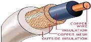
Figure 1: Coaxial cable
The coaxial cable offers at the same time a broad bandwidth
and an excellent immunity against the noise, his bandwidth depends on the
quality of the cable, its length and the signal to noise ratio, this type of
cable was largely employed within the telephone system on the trunk lines but
it is now replaced by optical fiber, especially on the long distance. It
however still very much used for the cable television and on the underground
railway networks.
The major disadvantages of copper are a strong attenuation and
a speed transmission relatively low which limits the maximum distance between
two stations or two apparatuses of interconnection
2.1.2.3 Waveguide
Waveguides are metallic transmission lines that are used at
microwave frequencies, typically to interconnect transmitters and receivers
We distinguish several forms such as:
> Rigid Guide with rectangular section

> Guide with circular section
> Flexible semi Guide with elliptic section etc
Waveguide has a number of advantages over coax, it is
completely shielded and excellent isolation between adjacent signals can be
obtained, it can transmit extremely high peak powers and it has very low loss
often almost negligible at microwave frequencies.[4]
One disadvantage of waveguide is its high cost, Manufacturing
volumes are low and waveguide materials such as copper and silver are
relatively expensive other disadvantages include unwieldy size and mass
particularly at lower frequencies.
2.1.2.4. Fiber optic
An optical fiber is a flexible, transparent fiber made of very
pure glass silica not much bigger than a human hair that acts as a waveguide,
or light pipe used to transmit light between the two ends of the fiber.
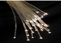
Figure 2: fiber optic
The optical fiber is used more depend on its exceptional
properties and particularly a very high bandwidth and a very weak attenuation
,it offers a flow of information definitely higher than that of coppers and
supports a network broadband by which can as well forward television,
telephony, the videoconference or the data information.[5]
The influence of optical fiber is the subject of our study,
particularly in a network multiservice and a deepening is reserved to him in
this chapter.

2.1.3 UNGUIDED MEDIA
2.1.3.1 Microwave link
A microwave link is a communications system that uses a beam
of radio waves in the microwave frequency range to transmit information between
two fixed locations on the Earth. They are crucial to many forms of
communication and impact a broad range of industries. Broadcasters use
microwave links to send programs from the studio to the transmitter location
which might be miles away, microwave links carry cellular telephone calls
between cell sites and Wireless Internet service providers use microwave links
to provide to their clients with high-speed Internet access without the need
for cable connections and Telephone companies transmit calls between switching
centers over microwave links, Although fairly recently they have been largely
supplanted by fiber optic cables
2.1.3.2 Satellite
In communications, satellite is a specialized wireless
receiver and transmitter that is launched by a rocket and placed in orbit
around the earth they are used for such diverse purposes as weather
forecasting, television broadcast, amateur radio communications, Internet
communications, and the Global Positioning System, (GPS).
After having given a general idea on the various media of
transmission, we will approach in the following the processes of optical fiber
for the routing with very great range of significant flows of information
integrated on the same line of transmission.
2.2 OPTICAL FIBER CABLE
To guide signals carrying information from a transmitter to a
receiver, the technique of telecommunications uses primarily two means such
as:
> Material support between the transmitter and the receiver;
> Transmission by radio waves.
Among the transmission material medium, best adapted for
significant traffics to high flow is the optical fiber; this is why, this
chapter is devoted to the meticulous treatment of this transmission
resource.
2.2.1 Definition
Fiber optics are long, thin strands of very pure glass about
the diameter of a human hair, They are arranged in bundles called optical
cables and used to transmit light signals over long distances that light
contains information which are being transmitted, the basic structure of an
optical fiber consists of three parts; the core, the cladding, and the coating
or buffer. The core is a cylindrical rod of dielectric material, Dielectric
material conducts no electricity, Light propagates mainly along the core of the
fiber, The core is generally made of glass, the core is described as having a
radius and an index of refraction. The core is surrounded by a layer of
material called the cladding, even though light will propagate along the fiber
core without the layer of cladding material, the cladding does perform some
necessary functions.[6]
The following picture shows the basic structure of the optic
fiber
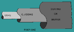
Figure 3 : Basic structure of an optical fiber
9
The cladding layer is made of a dielectric material with an
index of refraction; the index of refraction of the cladding material is less
than that of the core material. The cladding is generally made of glass or
plastic, the cladding performs the following functions it Reduces loss of light
from the core into the surrounding air, reduces scattering loss at the surface
of the core ,Protects the fiber from absorbing surface contaminants
For extra protection, the cladding is enclosed in an
additional layer called the coating or buffer. The coating or buffer is a layer
of material used to protect an optical fiber from physical damage, the material
used for a buffer is a type of plastic. [6]
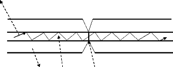
2.2.2 Principle of optical transmission.
The fiber carries a signal encoded beam of light by virtue of
total internal reflection (TIR). TIR occurs at the interface of a transparent
medium with another medium, if the transparent medium has a higher index of
refraction than the surrounding medium, TIR occurs. This makes the optical
fiber a waveguide for frequencies in the range 1014 to
1015 Hz, covering the visible and part of the Infrared spectrum
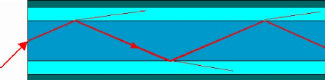
Figure 4 : Principle of optical transmission
The figure above illustrate the principle of total internal
reflection as used in fiber optical communications, Total internal reflection
is an optical phenomenon that happens when a ray of light strikes a medium
boundary at an angle larger than a particular critical angle with respect to
the normal to the surface. If the refractive index is lower on the other side
of the boundary, no light can pass through and all of the light is reflected.
The critical angle is the angle of incidence above which the total internal
reflection occurs.
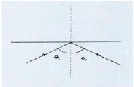
Figure 5: Total internal reflection
So the critical angle is defined as the angle of incidence that
provides an angle of refraction of 90-degrees.
Let's consider two different media creatively named medium i
(incident medium) and medium r (refractive medium). The critical angle is the
èi that gives a èr value of 90-degrees. If this
information is substituted into Snell's Law equation, a generic equation for
predicting the critical angle can be derived. The derivation is shown
below.[7]
ni
· sine(èi) = nr
· sine
(èr) (2.2)
when èr=900
ni
· sine(ècrit) = nr
· sine
(90 degrees) (2.3)
ni
· sine(ècrit) = nr
sine(ècrit) = nr/ni
ècrit = sine-1 (nr /ni) = arcsin
(nr/ni) (2.4)
Two stages transducers thus should be added (the equipment
intended to convert the signals), one at the beginning, to ensure conversion
electricity/light; the other on arrival for opposite conversion. In the first
case, it is about a laser diode or LED diode ; in the second a photo diode.
By convention, an impulse of light indicates a bit to 1 and
the absence of light to 0, But as any ray whose incidence reaches the critical
angle undergoes an internal reflection, many rays are propagated under various
angles in optical fiber. it is said that each one has a different mode a fiber
presenting this property is thus called fiber multimode.[8]
However, if the diameter of fiber is tiny in proportions such
as only one luminous ray can there be propagated, then the fiber acts like a
guide of waves and the light can be propagated only in straight line without
reflection is called a monomode fiber, it is more expensive than fiber
multimode but is largely used at longer distances because it transmit data to
50 Gbit/s out of 100 km without amplification.
2.2.3 Schrödinger wave equation
The Schrödinger equation is the fundamental equation of
physics for describing quantum mechanical behavior, it is also often called the
Schrödinger wave equation, and is a partial differential equation that
describes how the wave function of a physical system evolves over time.[9]
The time-dependent one-dimensional Schrödinger equation is
given by
2
2
2
~ ) ) ) 2 ~
where i is the imaginary unit, is the time-dependent wave
function, is h-bar, V(x) is the potential, and is the Hamiltonian operator,
However the equation can be separated into temporal and spatial parts using
separation of variables to write
) ) ) 2 )
thus obtaining
2

2
~
2
) I 2 7)
Where E represent the system energy
Setting each part equal to a constant then gives the time
independent Schrodinger equation for one dimension:
2 )1 ) ) (2.8)
where T(t) = e~
Ø(x,t) = (x)e~
2.2.4 Emission
The figure bellow shows the Emission block of fiber and LASER
diode as the source
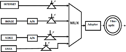
Figure 6 : Emission block of fiber optical signal and laser
diodes as the source.
The most commonly used optical transmitters are semiconductor
devices such as light-emitting diodes (LEDs) and LASER diodes, the difference
between LEDs and LASER diodes is that LEDs produce incoherent light, while
LASER diodes produce coherent light, for use in optical communications,
semiconductor optical transmitters must be designed to be compact, efficient,
reliable and directly modulated at high frequencies.
The power emitted by the LASER diode is calculated as follow:
P=h(I-Is) for I>Is and I<Is ,P=0 (2.9)
Where:
I: Injected current in LASER
Is: Threshold current of LASER
h: Gain of LASER
In an emissive transition, the energy of the photon created in
LED diode is given by the difference of the energy levels Ei (initial level of
energy ) and Ef (final level of energy ).
hv=Ei - Ef (Electron-volt) 2.2.5 Reception
The main component of an optical receiver is a photo-detector
which converts light into electricity using the photoelectric effect, the
photo-detector is typically a semiconductor-based photodiode.
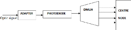
Figure 7 : Block scheme of fiber optic receiver
The significant parameters which characterize a photodiode are
: sensitivity, obscurity current , the response time, we can remove obscurity
current which circulates in the junction , in absence of illumination, thus
that current is not provident by photons transmitted by the fiber ,they can
have many sources like thermal generation in the intrinsic zone, currents of
surface.
The expression of the total current in photodiode is given by the
equation. Iph=S.Popt+Iobs (2.10)
Where:
Iph: Total current in photodiode
S: Sensitivity in photodiode
Popt :The optical power received by photodiode
Iobs:Obscurity current
2.2.6 TYPES OF FIBER OPTIC
According to the modes of propagations which they use, the
optical fiber can be classified in three categories such as: [8]
> Single mode Optical Fiber.
> Multimode Step Index fiber optic.
> Multimode Graded Index fiber optic.
2.2.6.1 Single mode fiber optic
The diameter of fiber being smaller, it transmits the signal on
only one luminous way, it is especially used for very long distances.
This type of fiber presents the greatest performances but its
cost is relatively high compared to multimode fiber.
Diameter of core 5 with 10um, cladding 125um;Very high bandwidth
and Very weak attenuation 0.5dB/km with 13um and 0.2dB/km with 1.5um very
delicate connections.
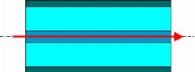
Figure 8 : Single mode fiber optic
2.2.6.2 Multimode step index fiber optic
The figure bellow corresponds to multimode propagation with a
refractive index profile that is called step index, when light enters the fiber
optic cable on the left, it propagates down toward the right in multiple rays
or multiple modes, the light is reflected angularly (in Zig-zag) .
This type of fiber contains : Diameter of the core 50um or 62.5um
generally cladding 1,25um Bandwidth of
60MHz.km and Weak attenuation:3dB/km with
jump 0,85um.
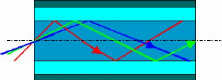
Figure 9 :Multimode step index fiber optic
For step index fiber the numerical aperture NA the angle which
light comes out of or goes into an optical fiber and acceptance angle èA
are given by the following formula [10]:
NA= /n -- n~ ~ (2.11)
Where n1 is the index of core and n2 is the index of the cladding
èA= sin-1(NA)
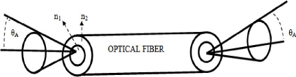
Figure 10 : Acceptance cone and acceptance angle in an optic
fiber.
2.2.6.3 Multimode graded index fiber optic
A graded-index fiber is an optical fiber whose core has a
refractive index that decreases with increasing radial distance from the fiber
axis because the core parts is closer to the fiber axis and have a higher
refractive index than the parts near the cladding then light rays follow
sinusoidal paths down the fiber.[10]
It has the following characteristics: Diameter of the core is
about 50um or 62,5um, cladding of 125um,Bandwidth is several
GHz.km and Attenuation is 3 dB/km with 0,85
um or 1,3um .
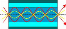
Figure 11: Multimode graded index fiber optic
2.2.7 ADVANTAGES AND DISADVANTAGES OF OPTICAL
TRANSMISSION
2.2.7.1 The advantages
The optical fiber present different advantages such as Low
transmission loss , Enormous Bandwidths, Immunity to cross talk and Electrical
Isolation, Small size and weight , Signal security, Ruggedness and flexibility,
Low cost and availability Reliability
2.2.7.2 The disadvantages
Difficulties of connection between 2 fibers, Difficult
Derivations, Difficulties on wave multiplexing, High cost of installation
Fragility.
2.2.8 APPLICATION OF FIBER OPTIC
Medical Used as light guides, imaging tools and also as lasers
for surgeries Data Used for data transmission
Telecommunications Fiber is laid and used for transmitting and
receiving purposes Networking Used to connect users and servers in a variety of
network settings and help increase the speed and accuracy of data
transmission
Industrial/Commercial Used for imaging in hard to reach areas,
as wiring where EMI is an issue, as sensory devices to make temperature,
pressure and other measurements and as wiring in automobiles and in industrial
settings
Broadcast/CATV
Broadcast/cable companies are using fiber optic cables for wiring
CATV,HDTV, internet video on-demand and other applications.
2.2.9 FIBER OPTIC CONNECTION
In the establishment of fiber optic link the following
constraints are meeting:
> The transmitting source with optical fiber. > The optical
fiber to optical fiber.
> The optical fiber with the optical receiver.
2.2.10 THE PRINCIPLE STRUCTURE OF FIBER OPTIC
2.2.10.1. Fiber optical multiplexing
Optical multiplexing also called Wavelength Divided
Multiplexing (WDM) or Dense Wavelength Divisions Multiplexing (DWDM) as
presented on the following figure actual this technology of WDM was born from
the idea of simultaneously injection of several trains of numerical signals at
the same speed of modulation into same optical fiber each one with distinct
wavelength.
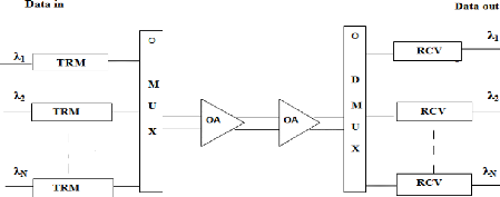
Figure 12 : Fiber optic multiplexing (WDM Point to Point).
The DWDM is the short form of Dense Wavelength Division
Multiplexing DWDM is an important technology in nowadays for fiber optic
network, DWDM use WDM technology to
arrange several fiber optic lights to transmit simultaneously via
the same single fiber optic cable, DWDM is usually used on fiber optic
backbones and long distance data.
2.2.10.2 Fiber optical modulation
We need a carrier signal high frequency for transmitting a
signal because a low level signal less power can not transmit over a long
distance, So modulation means to change some parameters (e.g phase, frequency
and amplitude) of the carrier in accordance to the message signal.
We have two types of modulation which are :
Analogue modulation( e.g Frequency modulation amplitude and phase
and Digital modulation(e.g pulse width modulation ,pulse code modulation...)
2.2.11 Maintenance of an optical link.
1. How do you repair a damaged fiber optic
cable
You have to locate the damaged area of the cable, this is
accomplished by an Optical Time Domain Reflectometer Based on the location of
the damage and what type of repair line level repair or depot maintenance level
either a splice or a pigtail assembly, and mechanical splices are under review
for approval and same redundant spare fiber or cable replacement can be
used.
2. How do you repair a fiber optic connector
You will need to perform a visual inspection of the connector
endface, using either a handheld optical microscope or a fiber optic video
probe, this procedure will determine the type of action needed to repair the
connector, If the connector only has minor damage, e.g: scratches, small chips,
or small pits, then re-polishing the connector will usually fix the problem if
the visual inspection determines that the connector is shattered or there is no
continuity then either a pigtail assembly will have to be spliced onto the
cable or the cable will need to be replaced utilizing a redundant spare fiber
for line level repair.
CHAPTER THREE: THE ANALYSIS OF FIBER OPTIC NETWORK IN
NUR
3.1 INTRODUCTION
Fiber optics uses light signals to transmit data as this data
moves across fiber there needs to be a way to separate it so that it gets to
the proper destination, There are two important types of systems that make
fiber to the home broadband connections possible, these are active optical
networks and passive optical networks each offers ways to separate data and
route it to the proper place
3.2 THE FIBER OPTIC LINK
A fiber optic link is a transmission media which connect two
points, at NUR the fiber optic comes from Kigali where the is a backbone office
to our campus at the NUR ICT CENTER, when we send signal from one customer to
the other we use that interconnection which consists of the sending station
that converts electrical signals into light signals and the receiving station
that convert the light signals back into electrical signals those signals
contains the information or data. [11]
In addition links are also described in terms of their ability
to send and receive signals they are divided into simplex and duplex system.
Simplex means that the link can only send at one end and
receive at the other end, the signals travels in one way and example can be the
signals from the Radio station.
Duplex stand for a link which can allow signals to be
transmitted and received at each terminates. It can be broken down into
half-duplex and full-duplex: half-duplex allows the signals to go only one way
at a time where full-duplex allows users to send and receive signals at the
same time for example a telephone communication.[11]
A fiber optic link consists of three basic components:
This following figure 13 shows the parts of an optical link and
the function of each components are illustrated below:
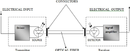
Figure 13 : Basic Optical System
Transmitter that convert the electrical signal input which can
be data pulse or analogue signals into variations of optical power at the
desired wavelength and send the light into the fiber ,the device to perform the
task is the light emitting diode LED or LASER diode .
The optical fiber that carries the light which provides the
communication medium. it can be single mode or multi-mode at our campus we use
single mode because it transmit data at long distance without attenuation .
Receiver which converts the received optical power from the
optical fiber back to the electrical signal and the device which performs the
tasks is the optical detector. and the signal is amplified to increase its
amplitude
Furthermore we have also what we call The connectors that
couple the optical fiber to the transmitter and receiver an example can be
pig-tails a short length of optical fiber with a connector fitted at one end
and the other end in intimate optical contact with the source.[11]
3.3 PASSIVE OPTICAL NETWORK.
A passive optical network (PON) is defined as optical access
networks that starts from an operator central office in my case study are MTN
fiber optic and RDB fiber to the individual homes here it is our campus NUR ICT
CENTER .
PONs are characterized by the absence of on any active
components it uses optical splitters to separate and collect optical signals
when they move through the network.
Furthermore PONs are also systems that brings all signals to the
customers according on where the PONs terminates.
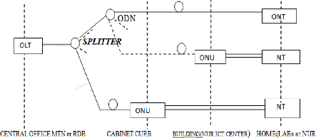
Figure 14. General structure of a PON
The figure 14 above explains how fiber optic arrives to the end
users whom can be The students
in the computer labs or on their laptops or
staff in their offices named home in the structure from
the central office called OLT ( Optical line termination) MTN
or RDB Central operators offices to the ONUs optical network unit According
where the fiber goes here it may be a cabinet distribution located at NYANZA or
same where else along the way from central offices all users have access to the
services offered by the network through the network terminal NT and to the
optical network through ONU or ONT. This OLT is the interface between all users
connected to the given PON.
Hence we have also ODN Optical distribution network which
works as the PON splitters they are used to share resources to the other users
in the same network by creating the link to the other customers they can be
arranged in star, ring or tree configurations to increase reliability.[12]
In addition according to the general structure of PON shown above
,PONs can be deployed in a FTTH fiber to home where an ONU is provided at the
subscriber?s premises or FTTB fiber to the building where the optical fiber
terminates before actually reaching the subscriber?s living or working space
itself , FTTC Fiber to the curb or cabinet this is installed in a street along
way side cabinet and is used as the connection between the OLT the central
office and the ONU which is the cabinet the local access network of the fiber
.[13]
3.3.1 ETHERNET PASSSIVE OPTIC NETWORK
Ethernet passive optical network EPON consists of an Optical
Line Termination (OLT) at the communication company's office and a number of
Optical Network Units (ONUs) near end users which are the cabinet distribution
centers and up to 32 ONUs can be connected to an OLT.
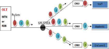
Figure 15 . Downstream Traffic Flow in an Ethernet PON
This figure 15 the data from the OLT to be sent to the
different ONUs must queue with no time delay between them in the EPON where
this serves as a trunk ,fiber optic link between a larger system and the home
Ethernet user hence splitter is used to separate packets according to theirs
respective destination .[14]
Downstream signals coming from the central office is broadcast
to each customer premises sharing a fiber and data Encryption is used to
prevent eavesdropping to keep the information out of the hands of unauthorized
people.
We have also the following figure for upstream data flow in the
EPON which shows as how packets are putted or uploaded on the network.
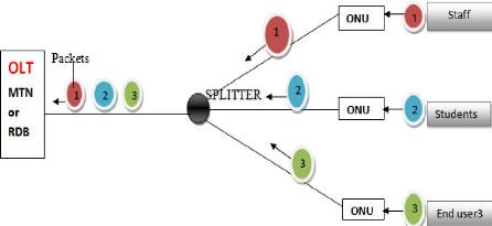
Figure 16. Upstream Traffic Flow in an Ethernet PON
The customer which is represented by an ONUs may need to
upload or sent packets to the other user in same or different network, Upstream
signals are combined using a multiple access protocol usually time division
multiple access (TDMA) then the OLTs range the ONUs packets in order to provide
time slot assignments for upstream communication without collisions and packets
fragmentation .[14]
3.3.2 BROADBAND PASSIVE OPTIC NETWORK
Broadband passive optical network is a wide band of
frequencies in the fiber optic connection which are available to transmit
information at high speed data rate and the information to be sent are
multiplexed before being put into the fiber. BPON systems can support downlink
performance of 155 to 622Mbit/s and uplink performance of 155 Mbit/s.[15]
3.3.3 GIGABIT PASSIVE OPTIC NETWORK
Gigabit Passive Optical Network GPON is an upgrade of BPON
with high speed data rates and this types of fiber is used to provider network
to the home .GPON is a point to multipoint access mechanism Its main
characteristic is the use of passive splitters in the fiber distribution
network enabling one single feeding fiber from the provider's central office to
serve multiple homes and small businesses at different places.
GPON has a downstream capacity of 2488 Mbits/s and an upstream
capacity of 1244 Mbit/s that is shared among users and Encryption is used to
keep each user's data secured and private from other users[16]
3.4 ACTIVE OPTICAL NETWORK
An active optical network (AON) is a system that uses
electrical powered switching equipment such as router and switch to manage
signal distribution and direct signals to specific customers.
At the termination point of the fiber at the NUR ICT CENTER
there is a semiconductor which converts optical signal into electrical signal
then a signal amplifier which increase the amplitude of the signal in order to
avoid signal attenuation that can cause the data to be loss hence comes switch
which divide the network into different parts depending on how they wants to
use it .
The most common type of active optical networks are called
active Ethernet this Active Ethernet uses optical Ethernet switches to
distribute the signal means that the internet network all over it is needed at
Ruhande.
This switch opens and closes in various ways to direct the
incoming and outgoing signals to the proper place in such a system a customer
may have a dedicated fiber running to his building.
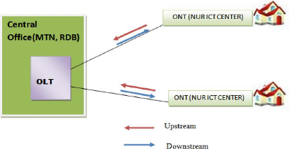
Figure 17 : Active optical network
Active optical network is a fiber to the building, this is NUR
ICT CENTER as optical network termination where all fibers connections ends
from the operators offices OLT before being distributed to the users of the
internet connections. User can also download and upload depending on his
need.[17]
3.5 SONET TECHNOLOGY
When data is transmitted over a communications medium a number
of things must be provided on the link including framing of the data, error
checking and the ability to manage the link. for optical communications these
functions have been standardized by the ANSI T1X1.5 committee as Synchronous
Optical Networking (SONET)
The information is sent over an optical fiber by turning the
light off and on in the fiber suppose that the presence of light is indicated
by «1» while the absence of light is indicates by «0» we
can
send and receive bits across an optical link and extract the
information from those bits by using SONET .
SONET is defined as the low level framing , rules which
governs the optical links By framing this means a block of bits (or octets)
that have a structure and which utilizes some technique to allow us to find the
boundaries of that frame structure ,Same parts of the block may be devoted to
overhead the network in order to provide the use of network management and
another parts will be dedicated to carrying payload or information we want to
communicate. [18]
3.6 FIBER OPTIC LOSSES 3.6.1 TYPES OF LOSSES
The word loss means attenuation or loss of optical power in
fiber optic itself, losses is valuable in designing and choosing components in
a fiber optic communications system, losses are also important variables in the
network design phase. There are different reasons for light losses which may
occur during transmission of light signal inside the fiber or during the
interconnection process of two fibers. [19]
Losses are expressed in decibels per kilometer (dB/km), in terms
of particular length L of a fiber the loss is expressed as:
Po=Pin10-áL/10 (3.1)
Where Po: The Power at a distance L from the input.
Pin: The Amount of Power coupled in the
fiber.
á: The fiber attenuation expressed in dB/km. Hence
attenuation in the fiber is
á=10[log(Pout /Pin )] /L expressed in dB/km (3.2)
The loss may be arise from different sources same are fiber
intrinsic loss which means that they occur due to the nature of the core
material and others are attenuation losses which may be caused by different
reasons.
We can explain same of the losses in the following paragraphs
3.6.1.2 Absorption Loss
This is due to the impurity such as metal particles or
moisture in the fiber and it can block some of the light energy which caused
absorption loss. it absorbs light and dissipate it in the form of heat
energy
The solution to this problem is to use ultra pure glass and add
Impurity chemicals to minimize impurities manufacturing so that Light can
travels best in clear substance .
light transmitted
Cladding fiber core connection
Figure 18 . Absorption loss
Absorption loss are due to the absorption of energy by
impurity ions that forms the core and hydroxyl radicals present in the core in
addition this causes the loss of signal means information along the
transmission.[19]
3.6.1.3 Rayleigh Scatter
Rayleigh scatter occurs when there are small changes in the
refractive index of materials in which the light signal travels, this loss is
caused by the miniscule variation in the composition and density of the optical
glass material itself.
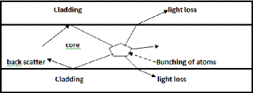
Figure 19 Rayleigh Scatter loss, The light can also be loosed
into the cladding or back scattered light that are caused by obstacle like
bunching of atoms in the core of the fiber .
3.6.1.4 Bending Loss
Bending losses occurs when a cable is bent and it disrupts the
path of the light signal the tighter the bends of a cable the greater it is of
the light loss.
Bending losses occurs here at those points
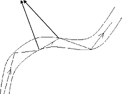
Figure 20 . Bending loss
Figure 20 shows the bending radius of an optical fiber that
result in light displacement caused by pinching or squeezing the fiber. Bending
deform the fiber's core slightly causing light to escape at these deflections,
The bend curvature creates an angle that is too sharp for the light to be
reflected back into the core and some of it escapes through the fiber cladding
hence the result is the optical power loss which increases rapidly as the
radius is decreased to an inch or less.[20]
3.6.1.5 Insertion Loss
Insertion loss is the most important performance indicator of
a fiber optic interconnection. this is the loss of light signal, measured in
decibels (dB) during the insertion of a fiber optic connector. Some of the
common causes of insertion losses includes: the misalignment of ferrules during
connection, the air gap between two mating ferrules and absorption loss from
impurities such as scratches and oil contamination
Insertion loss can be minimized by proper selection of
interconnect materials ,good polishing and termination process of fiber
connectors. [19]
3.6.1.6 Return Loss
Return loss which is also known as back reflection is the loss
of light signal that is reflected back to the original light source. this
occurs as the light is reflected off the connector and travels back along the
fiber to the light source It occurs also when there are changes in the
refractive index of materials in which the light travels such as the fiber core
and the air gap between fiber interconnection. When light passes through these
two different refractive indexes some of the light signal is reflected back.
[19]
CHAPTER FOUR: DISCUSSION AND INTERPRETATION OF THE
RESULTS
4.1 DISCUSSION OF THE NETWORK IN NUR
Before we were using the internet connection through satellite
which was in communication with an Earth Antenna VSAT(Very Small Aperture
Terminals ) this is type of antenna is chosen because is directional and very
focus in terrestrial signal transmission here it is a dish located at NUR main
library near NUR ICT center it?s bandwidth was about 2.5 Mbps download and 1.5
Mbps upload at that time connection was faster without interruption but the
cost was high and the bandwidth was small to serve all people in need of
internet connection at our campus it was shared by staffs only and few students
labs.
Nowadays, we have moved to the fiber optic network which is a
grounded optical fiber cable ,the first fiber being implemented was Rwandatel
which is no longer in use at this time then MTN this is currently used and RDB
pipeline which is for government sponsor and is connected to other fibers of
the regions in order to provide high connectivity all over the world and soon
it will be operational in our campus the implementation phase has finished now
it?s time for putting data or signal inside the pipeline .
In addition the type of fiber optic network used at NUR is
single mode fiber optic network because it transmit at long distances without
the attenuation in addition it has Very high bandwidth and Very weak
attenuation 0.5dB/km with 13um and 0.2dB/km with 1.5um very delicate
connections the attenuation occurs at each 100km this is where we can put a
repeater in order to increase signal amplitude and to avoid signal loss during
the transmission phase.
The fiber optic has contribute so much in the increasing of
bandwidth in NUR internet connection through cables and wireless connection now
we have the bandwidth of about 54Mbps upload and download and all over our
campus students and staffs can access the resources offered by the network.
4.2 FIBER OPTIC RESULTS IN BANDWIDTH AND YEARS IN NUR
NETWORK 7 1E0U4.1: U18 5 UNS 1' : , ' 7 + US 1' U 6311
|
YEARS
|
UPLOAD
|
DOWNLOAD
|
ISP PROVIDER
|
|
2005
|
1.5 Mbps
|
2.5 Mbps
|
SATELLITE CONNECTION
|
|
2006
|
1.5 Mbps
|
2.5 Mbps
|
SATELLITE CONNECTION
|
|
2007
|
2.5 Mbps
|
6 Mbps
|
RWANDATEL FIBER
OPTIC CABLE
|
|
2008
|
2.5 Mbps
|
6 Mbps
|
RWANDATEL and MTN FIBER OPTIC CABLE
|
|
2009
|
2.5 Mbps
|
6 Mbps
|
|
2010(2Qtr)
|
2.5Mbps
|
6 Mbps
|
|
2010(3Qtr)
|
17 Mbps
|
17 Mbps
|
|
2010(4Qtr)
|
27 Mbps
|
27 Mbps
|
|
2011(1Qtr)
|
17 Mbps
|
17 Mbps
|
MTN FIBER OPTIC CABLE
|
|
2011(2Qtr)
|
54 Mbps
|
54 Mbps
|
This table 4.1 shows us that by the time fiber optic being
installed in NUR the bandwidth has increased rapidly from 1.5 Mbps/2.5 Mbps by
2005 to 54 Mbps/54 Mbps by 2011(2Qtr) this is great positive impact of the
optical fiber transmission on the NUR network and this has been achieved with
the internet service provider ISP called MTN fiber optic cable.
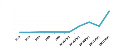
4.3 THE INCREASE IN BANDWIDTH CHART OF NUR INTERNET
BANDWIDTH IN Mbps
40
60
50
30
20
10
0
UPLINK
YEARS
Figure 21 . Uplink bandwidth connectivity assigned to NUR
This portion of a communications link is used for the
transmission of signals or data from NUR to a satellite or to a fiber optic
link.
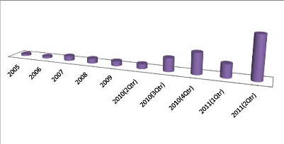
2.5 2.5 6 6 6 6 17 27
17
DOWNLINK
54
Figure 22 Downlink bandwidth connectivity assigned to NUR
This bandwidth is used by end users who can be a student or a
staff to get information from the internet.
These two figures: figure 21 and figure 22; we noticed that
the uplink speed is roughly equal to the downlink but at our campus we need
more to download than to upload because students are doing research and it is
often that we can upload sometimes we may need to send e-mails and files which
does not require us a huge bandwidth.
4.4 THE TRAFFIC MONITORING OF NUR INTERNET LINK
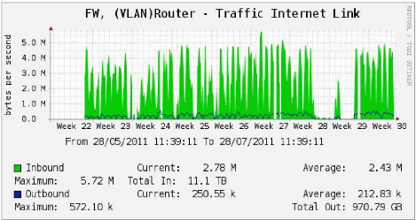
Figure 23 . The traffic internet link
This explains us the use of the bandwidth from 28/05/2011 at
11:39:11 to 28/07/2011 at 11:39:11 within two months ago where we see the white
from the week axis it was the problem of the fiber such as cut off or other
fiber losses in addition the green one shows the inbound maximum mean the used
bandwidth it was 5.72 Mbps and the outbound maximum means the unused bandwidth
was 572.10Kbps Where the peak is too high means the internet users are many on
the network and this occurs within the working hours of students and staffs,
this chart get automatic updates after each five minutes for any components to
work properly tit needs current which played a important role in the
transmission of data or any information through any medium.
CONCLUSION AND RECOMMENDATIONS
CONCLUSION
The main objective of this project was to evaluate the
advantages or benefits and the impact of fiber optics network that has
contribute in telecommunication field in NUR and this has been achieved
accurately.
Used effectively, the fiber optic network grounded wire has a
dramatic effect on the way of communication without any effect on the human
being because it does not radiate electromagnetic waves in space.
Today, fiber optic is used to the system great performance and
high data rate because of it s properties of conductivity which uses
total internal reflection of light inside the core with low loss of signal and
immunity to electromagnetic interference then low bit error rate and high
bandwidth towards the infinite .
Every Telecommunication company in Rwanda which need to
implement the fiber optic cable in our country has to dig and I see this as
challenge and I suggest that they could use one fiber for transmission in order
to do not loose resources for the same purpose.
My purpose in this domain in the next research ,people must
study the maintenance of this fiber because when it got trouble we need special
trained people in this domain and same times are from outside the country and
are high costly.
Furthermore my satisfaction in this project was the better
transmission of the fiber optic cable and low attenuation of this media
cable.
RECOMMANDATIONS We recommend:
> To NUR staffs especially those from NUR ICT CENTER to
provide easily full and rich
information to the students who are doing research on any
subjects concerned.
> To Internet Service Provider ISP in Rwanda to use fiber
optic transmission connection in
order to deliver good services to their clients.
> To Rwanda government to put much effort in the
implementation of this fiber optic network in order to achieve broadband
communication with others countries in the world and also SFAR to provide
certain sponsors for students who are doing their memories.
> To NUR Library to provide many books related to fiber optic
transmission because they are few.
> To the faculty of Applied Sciences to provide the
laboratories accessibility that could help the students in their research and
for other needed knowledge.
REFERENCES
[1] Katsunari Okamoto, fundamentals of optical waveguides,
Academy press, second edition, December 27, 2005.
[2] Alberto Leo-Garcian, (2003), Communication Network, second
edition, McGraw-Hill Higher Education.
[3] Steven Karris, (2009), Networks Design and Management ,
Second Edition ,Orchard.
[4] Eduard Sackinger ,Broadband Circuits for Optical Fiber
Communication, 2005
[5] Casimer M. DeCusatis and Carolyn J. Sher DeCusatis (2006)
Fiber optic essentials.
[6] John A. Buck,(2004), Fundamentals of optical fibers ,Second
Edition , New Jersey.
[7] Prof. Dr. Fedor Mitschke (2009) Fiber Optics Physics and
Technology, Springer-Verlag Berlin Heidelberg.
[8] Richard C. Dorf, (2006), Broadcasting and Optical
Communication Technology, Third Edition . Taylor & Francis Group.
[9] David J.Griffiths (2004).Introduction to Quantum
Mechanics (2nd ed.). Benjamin Cummings. ISBN 0131244051.
[10] John Crisp and Barry Elliot (2005),Introduction to Fiber
Optics Third edition, Elsevier Linacre House.
[11] D. B. Payne and R. P. Davey, "The Future of Fiber Access
Systems,» BT Technology Journal, vol. 20, 2002.
[12] Lam, Cedric F.(2007) "Passive Optical Networks: Principles
and Practice. San Diego, California.
[13] Bishnu P. Pal ,(2006 ) ,Guided wave Optical components and
devices, Basics and Technology Applications , Elsevier Inc.
[14] Kramer, Glen, Ethernet Passive Optical Networks,
McGraw-Hill Communications Engineering, 2005.
[15] Achyut K. Dutta ,Niloy K. Dutta and Masahiko Fujiwara
(2003), WDM Technologies Passive Optical components Volume II ,Elsevier Science
(USA).
[16] Rec. G.984, Gigabit-capable Passive Optical
Networks (GPON), ITU-T, 2003.
[17] Anders Gavler, Pontus Sköldström and Viktor
Nordell. (2010) ,Advances in Active Optical Networks (AON), Acreo Netlab,
Sweden.
[18] Werner Habisreitinger.(1980 ),Fundamentals and SONET
Testing, Acterna Germany GmbH.
[19] S. C. Gupta. (2004), Textbook on optical fiber
communication and its applications, Prentice-Hall India.
| 

