|

NATIONAL UNIVERSITY OF RWANDA
i
FACULTY OF SCIENCE AND TECHNOLOGY
DEPARTMENT OF
COMPUTER SCIENCE
IP PACKET CHARGING MODEL FOR
MULTIMEDIA SERVICES
Submitted in partial fulfilment of the requirements
for the award of Bachelor's degree in Computer Science
By:
KAYISINGA JEAN DE
DIEU
&
SAIDI SAIBA
Director:
Mr. ASHRAPH Sulaiman
Huye, February 2007

DEDICATION
To the Almighty Godfor his guidance and protection
To
myparents
To my sister and brothers
To all myfriends and
relatives
KAYISINGA Jean de Dieu
To the Almighty Godfor his guidance and protection
To my
dearest parents
To my late aunt GAHONGA VIRE
To my late brother AMADA
Saiba
To my appreciate brothers, sisters and cousins
To all of
mine
ii
ACKNOWLEDGEMENT
Our sincere thanks go first and foremost to Mr. ASHRAPH
Sulaiman for having accepted to supervise this dissertation despite his
enormous responsibilities. Without his guidance, support and advice, we would
not have succeeded in finishing this work.
We also thank all the lecturers in the Faculty of Applied
Science and the Faculty of Science and Technology especially those of the
Computer Science department for the intellectual package they provided us.
Special thanks go to Dr. SAHINGUVU William, for his remarkable contribution
along our research project. Particular thanks to the National University of
Rwanda and the Rwandan Government for having given us opportunities to get
these skills.
Our sincere gratitude goes to NUR Computing Center staff,
especially the Managing Director Mr. NKURIKIYIMFURA Didier and Mr. Vincent
DEMARQUE for their collaborating efforts to provide needed information and
materials to the achievement of desired goals of this project.
Special thanks go to our friends NSHIMIYE RWAKIGARAMA Michel,
MANZI KAREKEZI Michel, KABANDANA Jacques, Ir. MAZIMA Georges, KAYUMBA Fred, and
NIYIBIZI Jean Paul who have been there when we need them and for their great
affection.
We are also very grateful to our parents, relatives, different
families and friends for their valuable support through out the years of our
education.
We would not forget to appreciate the company and friendship from
our colleagues especially those who contributed to the completion ofthis
work.
YO U DESER VE O UR SINCERE APPRECIA
TIONS.
MAY GOD BLESS YOUALL.
iii
TABLE OF CONTENTS
DEDICATION i
ACKNOWLEDGEMENT ii
TABLE OF CONTENTS iii
ACRONYMS v
LIST OF FIGURES vii
LIST OF TABLES viii
ABSTRACT ix
SOMMAIRE x
CHAPTER I: GENERAL INTRODUCTION 1
I.1. Background 1
I.2. Introduction 1
I.3. Statement of the problem 2
I.4 Objectives ofthe study 3
I.5. Hypothesis ofthe study 3
I.6. Methodology 3
I.7. Interest of the project 4
I. 7.1. Personal interest 4
I.7.2. Community interest 4
I.8. Approach to the study 4
I.9. Scope ofthe project 4
I.10. Organization of the study 5
CHAPTER II: THEORITICAL CONCEPTS 6
II.1. COMPUTER NETWORK BASICS 6
II.1.1. NET WORK DE VICES 6
II.1.2. LAN 7
II.1.3. WAN 8
II.1.4.MAN 9
II.1.5.SWITCHING 10
II.2 OSI MODEL AND TCP/IP 14
II.2.1 THE SEVENLA YERS MODEL 14
II.2.2 TCP/IP AND UDPPROTOCOLS 15
II.3 QUEUING DELAY AND JITTER BUFFER 21
II.3.1 BUFFER 21
II.3.2 JITTER BUFFER 22
II.3.3 QUEUINGDELAY 23
II.3.4 LA TENCY 23
II.4 QUALITY of SERVICE 24
II.4.1 INTRODUCTION 24
II.4.2 QoS CONCEPTS 24
II.4.3 BASIC QoS ARCHITECTURE 25
II.4.4 QoS WITHINA SINGLE NETWORK ELEMENT 26
II.5 MULTIMEDIA OVER IP 27
II.6 STREAMING PROCESS 33
II.6.1 STREAMING 33
II.6.2 UNICAST 33
II.6.4BROADCAST 36
II.7 MULTIMEDIA APPLICATIONS 39
CHAPTER III: RESEARCH METHODOLOGY AND ANALYSIS OF MULTIMEDIA
SERVICES 44
III.1 Introduction 44
III.2 Section approach 44
III.2.1 Concepts 45
III.2.2 Notations 45
III.2.3 Process 45
III.2.4 Pragmatics 45
III.3 Live media model Analysis 46
III. 3.1 TRADITIONNAL STREAMING 46
CHAPTER IV: ANALYSIS AND IMPLEMENTATION OF LIVE VIDEO
STREAMING 50
IV. 1 Introduction 50
IV.2 Shoutcast configuration 52
IV.2. 1 STAR T SHOUTCAST CONFIGURATION 52
IV. 2.2 WARNING CONFIGURATION 52
IV. 2.3 SHOUTCAST CONFIGURATIONFILE 53
IV.3 live video streaming using nsv capture 53
IV. 3.1 SET CAPTURE DESTINATION 54
IV. 3.2 SET CAPTURE DESTINATION FILE 54
IV. 3.3 NVS tools FOR DE VICES 55
IV. 3.4 SET CAPTURE DESTINATION 55
IV. 3.5 VIDEO DECODER CONFIGURATION 57
IV. 3.6 VIDEO CAPTURING PIN CONFIGURATION 58
IV. 3.7 VIDEO CAPTURING CONFIGURATION 58
IV.4 Results analysis 61
CHAPTER V: CONCLUSION AND RECOMMENDATIONS 69
REFERENCES 70
ACRONYMS
: : : : : : : : : : : : : : : : : : : : : : : : : : : : : : :
:
ATM CBWFQ CD
CPU CQ
DirectTV DNS DTX ETSI
ES
FDDI FIFO GB
GHz ICMP IHL InterNIC IP
IS
ISP
kHz
LAN MAN MB
Mbps MIDI MPEG MTN MTU NSP NSV NSVcap
Asynchronous Transfer
Mode Class-Based
Weighted Fair Queuing
Compact Disc
Central Processing
Unit
Custom Queuing
Direct TeleVision
Domain Name
System
Discontinuous Transmission
European Telecommunications
Standards Institute. End
System
Fiber-Distributed
Data Interface First
In First Out
Giga Bytes
Giga Hertz
Internet Control
Message Protocol IP
Header Length
Internet Network
Information Center Internet
Protocol
Intermediate Systems
Internet Service
Provider Kilo
Hertz
Local Area
Network
Metropolitan Area
Network MegaByte
Mega bytes per
second
Musical Instrument
Digital Interface Moving
Picture Experts Group
Mobile Telephone Network
Maximum-Transmission Unit
Network Service Providers
Nullsoft Streaming
Video Nullsoft Streaming
Video Capture
vi
: : : : : : : : : : : : : : : : : : : : : : : : : : : : : : :
:
NTSC OS' PAL
PC
PC'
PQ
PS
QoS RAM RG RGB RRe
RR RSVP RTCP RTP RTSP SDES SONET SR
SVideo TCP
TV UDP UK VAD VCR VHS Vo'P WAN WFQ WLAN WRED
National Television
Systems Committee Open
Systems Interconnection
Phase-Alternating Line
Personal Computer
Peripheral Component
Interconnect Priority
Queuing
Packet Switching
Quality of Service
Random Acces s
Memory
Resource Grants
Red Green Blue
Receiver Report Resource
Request
Resource
ReServVation Protocol
Real-Time Control
Protocol
Real-time Transport
Protocol Real-Time
Streaming Protocol
Source Description
Items
Synchronous Optical
Network
Sender Report
Super Video
Transmission Control
Protocol Television
User Datagram
Protocol
United Kingdom
Voice Activity
Detection
Video Cassette
Recorders
Video Home
System
Voice over
Internet Protocol
Wide Area
Network Weight Fair
Queue Wireless Local
Area Network
Weighted early random
LIST OF FIGURES
Figure 1: WAN topology (Typical "mesh" connectivity of a Wide
Area Network) 9
Figure 2: A connection between two systems A & D formed from
3 links 10
Figure 3: A circuit switched connection between A and D 11
Figure 4: Communication between A and D using circuits which
shared dusing PS 13
Figure 5: Packet-switched communication between systems A and D
13
Figure 6: OSImodel 15
Figure 7: IP packet Datagram 17
Figure 8: IP address consists of 32 bits, grouped into four
octets. 19
Figure 9: UDP encapsulation 20
Figure 10: UDP segment structure 20
Figure 11: A Basic QoS Implementation Has Three Main Components
25
Figure 12 : High Level Network diagram for UNICAST 34
Figure 13 : High Level Network for MULTICAST 35
Figure 14: Broadcasting process 37
Figure 15: High level Network Architecture of live video
streaming 38
Figure 16: HiperLAN/2 QoS Architecture 41
Figure 17: Packet Scheduling 42
Figure 18: Traditional streaming diagram 46
Figure 19: Bandwidth diagram for traditional streaming 48
Figure 20: PCs connection diagram 51
Figure 21: Start shoutcast server 52
Figure 22: Warning of configuration 52
Figure 23: Shoutcast configuration file 53
Figure 24: NSV tools configuration to set capture destination
54
Figure 25: Set capture destination 54
Figure 26: NVS tools for capturing cards 55
Figure 27: Selection ofvideo input 56
Figure 28: Video capture filter configuration 56
Figure 29: Video Decoder configuration 57
Figure 30: Video Proc Amp 57
Figure 31: Video Capture pin 58
Figure 32: Video capture configuration 59
Figure 33: NSV configuration 59
Figure 34: NSV encoder configuration 60
Figure 35: The first image to send to the client 60
Figure 36: starting capturing the image 61
Figure 37: Intrastation packets scheduling 63
Figure 38: Interstation packets scheduling 65
Figure 39: Comparative diagram between packet charging model and
traditional streaming 66
LIST OF TABLES
Table 1: Bandwidth test for traditional streaming 47
Table 2: PCs specification 51
Table 3: latency test 62
Table 4: Intrastation packets scheduling 63
Table 5: Interstation packets scheduling: 64
Table 6: Comparative table 65
Table 7: Packets loss inside the network 66
ABSTRACT
IP packet charging model is an important component of networking.
However this is not mostly used by multimedia users, and yet it has many
advantages.
This work presents the techniques of live video streaming and
analyze high performance and quick relay of multimedia services especially for
live video streaming.
Our contribution concerns two essential parts:
In the first place there is a theoretical part. This part puts
in evidence the concepts of the multimedia as well as those of the streaming,
packets scheduling concepts and protocols used when doing real time streaming
in a detailed way.
The second part which is the practical part is made in four
stages:
1. Network analysis based on testing latency, bandwidth and
packets loss when there is traffic ofpackets when using traditional
streaming.
2. The implementation of IP packet charging model for
multimedia services which has been focusing on live video streaming by using
Shoutcast as a streaming server and Nullsoft tools as encoder tools that help
to convert video into streamable format.
3. Network analysis after implementing IP packet charging
model
4. The finally thing was about conclusion and recommendation of
the study which showed advantages ofusing IP packet charging model.
SOMMAIRE
Le modèle de chargement de paquet d'IP est une
important partie de la gestion de réseau. Cependant ceci n'est pas
employé par des utilisateurs de services multimédia la plupart du
temps, et pourtant ceci présente d'avantages.Ce travail présente
les techniques de vidéo streaming et analyse le rendement
élevé et le relais rapide des services multimédia
particulièrement pour le vidéo streaming. Notre contribution
concerne deux parts essentielles :
Il y a en premier lieu une revue théorique. La
présente partie met en évidence les concepts de multimédia
comme ceux de streaming, des concepts d'ordonnancement de paquets et des
protocoles intervenant pendant la réalisation du streaming en temps
réel dans une manière détaillée.
La deuxième partie qui est la partie pratique est faite
dans quatre phases:
1. Analyse de réseau basé sur la latence, la bande
passante et la perte de paquets pendant le trafic des paquets en utilisant le
streaming traditionnel.
2. L'exécution du modèle de chargement de
paquet d'IP pour des services multimédia en général, et
particulièrement le vidéo streaming en employant Shoutcast comme
serveur streaming et des outils développer par Nullsoft comme outils
d'encodage qui aident à convertir la vidéo en format capable
d'être streamé.
3. Analyse de réseau après avoir fait la mise en
application du modèle de chargement de paquet d'IP.
4. la dernière étape était de conclure
et de faire les recommandations de l'étude en montrant les avantages
d'employer le modèle de chargement de paquet d'IP.
CHAPTER I: GENERAL INTRODUCTION
Background
Internet Protocol (IP) Multimedia requires the support of
guaranteed services and charging to provide a valuable service for potential
customers. The quality of long distance Multimedia files via the Internet is
heavily affected by the load of the links that the traffic of data (Multimedia
files) has to traverse. As different quality requirements of users exist, the
Internet has to support different service classes. Therefore, an advanced
services network model is required.
In turn, and that is the main motivation for this work, if at
least two traffic classes exist on the Internet, the right incentive must exist
for any user to choose the traffic class that optimally fits the necessary
requirements and will be the most efficient in terms ofprice to be paid.
Therefore, the integration of IP packet charging model and
Quality-of-Service (QoS) interfaces for IP in multimedia services is important
to stimulate the future use of the Internet. This work gives an overview of IP
packet charging model for multimedia services, an experimental Platform for
standards-based IP Multimedia that are enhanced with QoS and packet charging
support.
I.1. Introduction
The traffic of multimedia services is the one that occupy a
large bandwidth in a network, now days the growth of this traffic is becoming
significant that can cause many failures inside a network.
send all file packets inside the network, and the aims of giving
IP are addressing and choosing the best path for the packets to reach
destination.
This project set out to implement an IP packet charging model
inside a network with the main objective of maintaining the Quality of
Services, The traditional way of handling this is to integrate QoS mechanisms
with the application logic, i.e., making the components self-adaptive.
I.3. Statement of the problem
Network connection are able to carry many types of services
such as voice, data, images, and video (flow of packets).This study deals with
problems of streaming video, in traditional streaming, buffer are used in order
to transfer data, and the QoS is still not satisfactory because of many
features like packets loss (which is very high), latency time is great and the
bandwidth is saturated.
However, IP multimedia provides services based on Internet and
it is concerned with multimedia data transmission. The selection of destination
address and choice of multimedia services quality is required in order to get
an easy transmission of multimedia services.
Traditional streaming used to send packets inside the network
without using packets switching which decreased the number of packets inside
the network and cannot improve the high performance and quick relay of
multimedia services, which means there is:
> A high bandwidth used during packets traffic. > A great
latency time.
> A great number ofpackets lost during the traffic
As solution, IP packet charging models for Multimedia services
was been chosen, which could help to solve the problem of charging data to the
appropriate destination. In this project understanding how packet switching and
circuit switching work is helpful because it can be used when transmitted
multimedia services.
I.4 Objectives of the study
The principal objective of this project is:
> To analyze network performance when using traditional
streaming and packets charging models
> To analyze queuing delay and jitter buffer during
traffic.
> IP packet charging model implementation for multimedia
services
> To analyze QoS variation during packets traffic i.e.
latency, jitter and bandwidth variation.
I.5. Hypothesis of the study This project aims
at verifying the following hypothesis:
«It is possible to implement the IP packet charging models
for Multimedia Services in order to get a high performance and quick relay of
multimedia services.»
I.6. Methodology
A methodology is a series of choices such us choices about
what information and data to gather, Choices about how to analyze the
information and data that you gather and other methodological choices. In This
project the choice made is the one that helped to analyze the network by making
comparison and it is called a comparative research.
Comparative methodology is the act of comparing two or more
things with a view to discovering something about one or all of the things
being compared. This technique often utilizes multiple disciplines in one
study.
When it comes to method, the majority agreement is that there
is no methodology particular to comparative research. 1In this case
the comparison done between traditional streaming and IP packet charging models
in a network.
1
http://en.wikipedia.org/wiki/Comparative_research,September
24, 2006
I.7. Interest of the project I.7.1. Personal
interest
Working on this project is acquire the practical experience
in networking (in general) and in IP network (in particular) that didn't
acquire before, by gathering different concepts from different courses studied
during our graduate program, and put up a system that is helpful.
I.7.2. Community interest
Like the National University of Rwanda many other
organizations, like MTN (Mobile Telephone Network) and other companies that
require Multimedia files traffic, this project through the use of IP packets
charging models technology would provide a cost effective technic for using
their existing network infrastructure to make a good Quality of Services to
their customers.
I.8. Approach to the study
The study will be focused on network performance during
Multimedia traffics. It is composed ofthe following phases:
> Requirement analysis
> Implementation
> Testing
> Operations & Maintenance
I.9. Scope of the project
The scope of this work is to implement IP packets charging
models for multimedia services such as text, image, audio, and video and so on,
but in this project multimedia focused on is video, with this live video
streaming will be done and the problem of buffering (packets loss) will be
treated as well. All this will help to show a video in real time.
I.10. Organization of the study This study is
organized in chapters:
Chapter 1: This chapter concerns the general introduction about
the project Chapter 2: This chapter concerns the theoretical concepts related
to the project
Chapter 3: This chapter concerns the research methodology and
analysis of
multimedia services.
Chapter 4: This chapter focuses on the implementation ofIP packet
charging model for multimedia services
Chapter 5: The last Chapter is focusing for Conclusion and
Suggestions.
CHAPTER II: THEORITICAL CONCEPTS
II.1. COMPUTER NETWORK BASICS
An internet work is a collection of individual networks,
connected by intermediate networking devices, that functions as a single large
network. The networking devices are the vital tools for communication.
Whenever they have a set of computers or networking devices to
be connected, they make the connections, depending on the physical layout and
their requirements Depending on the physical layout or topology of the network,
there are many types of networks topologies, but in this project let talk about
Local Area Network(LAN) and Wide Area Network(WAN).
II.1.1. NETWORK DEVICES
II.1.1.1.Router
A router is a device that forwards data packets along
networks. A router is connected to at least two networks, commonly two LANs or
WANs or a LAN and its ISP's network. Routers are located at gateways, the
places where two or more networks connect.
Routers use headers and forwarding tables to determine the
best path for forwarding the packets, and they use protocols such as ICMP to
communicate with each other and configure the best route between any two hosts.
2
2
http://www.webopedia.com/TERM/r/router.html,
February 1,2007
II.1.1.2. Switch
A switch is used in a wired network to connect Ethernet cables
from a number of devices together. The switch allows each device to talk to the
others. (Switches aren't used in networks with only wireless connections, since
network devices such as routers and adapters communicate directly with one
another, with nothing in between.)3
II.1.2. LAN
The Local Area Network (LAN) is by far the most common type of
data network. As the name suggests, a LAN serves a local area (typically the
area of a floor of a building, but in some cases spanning a distance of several
kilometers).
Typical installations are in industrial plants, office
buildings, college or university campuses, or similar locations. In these
locations, it is feasible for the owning Organization to install high quality,
high-speed communication links interconnecting nodes. Typical data transmission
speeds are one to 100 megabits per second.
A wide variety of LANs have been built and installed, but a
few types have more recently become dominant. The most widely used LAN system
is the Ethernet system developed by the Xerox Corporation.
Intermediate nodes (i.e. repeaters, bridges and switches)
allow LANs to be connected together to form larger LANs. A LAN may also be
connected to another LAN or to WANs and MANs using a "router".
In summary, a LAN is a communications network which is:
· local (i.e. one building or group of buildings)
· controlled by one administrative authority
· assumes other users of the LAN are trusted
· usually high speed and is always shared
3
http://kbserver.netgear.com/kb_web_files/n101528.asp,
February 1, 2007
LANs allow users to share resources on computers within an
organization, and may be used to provide a (shared) access to remote
organizations through a router connected to a Metropolitan Area Network (MAN)
or a Wide Area Network (WAN).4
II.1.3. WAN
The term Wide Area Network (WAN) usually refers to a network
which covers a large geographical area, and use communications circuits to
connect the intermediate nodes. A major factor impacting WAN design and
performance is a requirement that they lease communications circuits from
telephone companies or other communications carriers.
Numerous WANs have been constructed, including public packet
networks, large corporate networks, military networks, banking networks, stock
brokerage networks, and airline reservation networks.
Some WANs are very extensive, spanning the globe, but most do
not provide true global coverage. Organizations supporting WANs using the
Internet Protocol are known as Network Service Providers (NSPs). These form the
core of the Internet.
By connecting the NSP WANs together using links at Internet
Packet Interchanges (sometimes called "peering points") a global communication
infrastructure is formed. NSPs do not generally handle individual customer
accounts (except for the major corporate customers), but instead deal with
intermediate organizations whom they can charge for high capacity
communications.
They generally have an agreement to exchange certain volumes
of data at a certain "quality of service" with other NSPs. So practically any
NSP can reach any other NSP, but may require the use of one or more other NSP
networks to reach the required destination. NSPs vary in terms of the transit
delay, transmission rate, and connectivity offered.
4
http://www.erg.abdn.ac.uk/users/gorry/course/intro-pages/lan.html
, September 12,2006
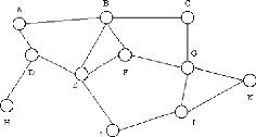
Figure 1: WAN topology (Typical "mesh" connectivity of a
Wide Area Network) Source:
http://www.erg.abdn.ac.uk/users/gorry/course/intro-pages/wan.html,september
22,2006
A typical network is shown in the figure above. This connects
a number of End System (ES) (e.g. A, C, H, K) and a number of Intermediate
Systems (IS)(e.g. B, D, E, F, G, I, J) to form a network over which data may be
communicated between the End Systems (ES).
The characteristics of the transmission facilities lead to an
emphasis on efficiency of communications techniques in the design of WANs.
Controlling the volume of traffic and avoiding excessive delays is important.
Since the topologies of WANs are likely to be more complex than those of LANs,
routing algorithms also receive more emphasis.
Many WANs also implement sophisticated monitoring procedures
to account for which users consume the network resources. This is, in some
cases, used to generate billing information to charge individual
users.5
II.1.4. MAN
Short for Metropolitan Area
Network, a data network designed for a town or city.
In terms of geographic breadth, MANs are larger than local-area networks
(LANs), but smaller than widearea networks (WANs). MANs are usually
characterized by very high-speed connections using fiber optical cable or other
digital media. 6
5
http://www.erg.abdn.ac.uk/users/gorry/course/intro-pages/wan.html,
September 12,2006
6
http://www.webopedia.com/TERM/M/MAN.html,
September 12,2006
II.1.5. SWITCHING II.1.5.1.
CIRCUITSWITCHING
Circuit switching is the most familiar technique used to
build a communications network. It is used for ordinary telephone calls. It
allows communications equipment and circuits, to be shared among users. Each
user has sole access to a circuit (functionally equivalent to a pair of copper
wires) during network use. Consider communication between two points A and D in
a network. The connection between A and D is provided using (shared) links
between two other pieces of equipment, B and C.
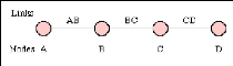
Figure 2: A connection between two systems A & D
formed from 3 links
Source:
http://www.erg.abdn.ac.uk/users/gorry/course/intro-pages/cs.html,
September 12, 2006
Network use is initiated by a connection phase, during which
a circuit is set up between source and destination, and terminated by a
disconnect phase. These phases, with associated timings, are illustrated in the
figure below.
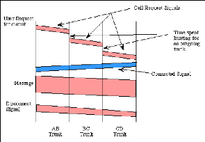
Figure 3: A circuit switched connection between A and
D
Source:
http://www.erg.abdn.ac.uk/users/gorry/course/intro-pages/cs.html,
September 12, 2006
Figure 3 shows how Information is flowing in two directions.
Information sent from the calling end is shown in pink and information returned
from the remote end is shown in blue.
After a user requests a circuit, the desired destination
address must be communicated to the local switching node (B). In a telephony
network, this is achieved by dialing the number.
Node B receives the connection request and identifies a path
to the destination (D) via an intermediate node (C). This is followed by a
circuit connection phase handled by the switching nodes and initiated by
allocating a free circuit to C (link BC), followed by transmission of a call
request signal from node B to node C. In turn, node C allocates a link (CD) and
the request is then passed to node D after a similar delay.
The circuit is then established and may be used. While it is
available for use, resources (i.e. in the intermediate equipment at B and C)
and capacity on the links between the equipment are dedicated to the use of the
circuit.
After completion of the connection, a signal confirming
circuit establishment (a connect signal in the diagram) is returned; this flows
directly back to node A with no search delays since the circuit has been
established. Transfer of the data in the message then begins. After data
transfer, the circuit is disconnected; a simple disconnect phase is included
after the end ofthe data transmission.
Delays for setting up a circuit connection can be high,
especially if ordinary telephone equipment is used. Call setup time with
conventional equipment is typically on the order of 5 to 25 seconds after
completion of dialing. New fast circuit switching techniques can reduce delays.
Trade-offs between circuit switching and other types of switching depend
strongly on switching times. 7
II.1.5.2. PACKET SWITCHING
Packet switching is similar to message switching using short
messages. Any message exceeding a network-defined maximum length is broken up
into shorter units, known as packets, for transmission; the packets, each with
an associated header, are then transmitted individually through the network.
The fundamental difference in packet communication is that the data is formed
into packets, and well-known "idle" patterns which are used to occupy the link
when there is no data to be communicated.
Packet network equipment discards the "idle" patterns between
packets and processes the entire packet as one piece of data. The equipment
examines the packet header information (PCI) and then either removes the header
(in an end system) or forwards the packet to another system. If the out-going
link is not available, then the packet is placed in a queue until the link
becomes free. A packet network is formed by links which connect packet network
equipment.
7
http://www.erg.abdn.ac.uk/users/gorry/course/intro-pages/cs.html,
September 12,2006
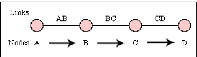
Figure 4: Communication between A and D using circuits
which shared dusing PS. Source: Own drawing
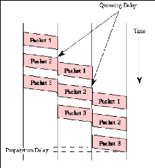
Figure 5: Packet-switched communication between systems
A and D Source:
http://www.erg.abdn.ac.uk/users/gorry/course/intro-pages/ps.html
Figure 5 illustrate how message has been broken into three parts
labeled 1 to 3 There are two important benefits from packet switching.
1. The first and most important benefit is that since packets
are short, the communication links between the nodes are only allocated to
transferring a single message for a short period of time while transmitting
each packet. Longer messages require a series of packets to be sent, but do not
require the link to be dedicated between the transmission of each packet. The
implication is that packets
belonging to other messages may be sent between the packets
of the message being sent from A to D. This provides a much fairer sharing of
the resources of each ofthe links.
2. Another benefit ofpacket switching is known as
"pipelining". Pipelining is visible in the figure above. At the time packet 1
is sent from B to C, packet 2 is sent from A to B; packet 1 is sent from C to D
while packet 2 is sent from B to C, and packet 3 is sent from A to B, and so
forth. This simultaneous use of communications links represents a gain in
efficiency; the total delay for transmission across a packet network may be
considerably less than for message switching, despite the inclusion of a header
in each packet rather than in each
8
message.
II.2 OSI MODEL AND TCP/IP II.2.1 THE SE VEN LAYERS MODEL
Seven layers are defined:
Application: Provides different services to
the applications and describes how real work actually gets done. This layer
would implement file system operations.
Presentation: Converts the information and
describes the syntax of data being transferred. This layer describes how
floating point numbers can be exchanged between hosts with different math
formats.
Session: Handles problems which are not
communication issues and describes the organization of data sequences larger
than the packets handled by lower layers. This layer describes how request and
reply packets are paired in a remote procedure call.
Transport: Provides end to end communication
control and describes the quality and nature of the data delivery. This layer
defines if and how retransmissions will be used to ensure data delivery.
8
http://www.erg.abdn.ac.uk/users/gorry/course/intro-pages/ps.html,September
12,2006
Network: Routes the information in the
network and describes how a series of exchanges over various data links can
deliver data between any two nodes in a network. This layer defines the
addressing and routing structure of the Internet.
Data Link: Provides error control between
adjacent nodes and describes the logical organization of data bits transmitted
on a particular medium. This layer defines the framing, addressing and check
summing of Ethernet packets.
Physical: Connects the entity to the
transmission media and describes the physical properties of the various
communications media, as well as the electrical properties and interpretation
of the exchanged signals. This layer defines the size of Ethernet coaxial cable
and the termination method.9
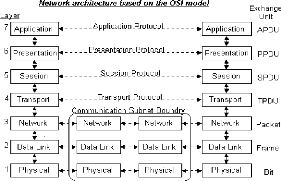
Figure 6: OSI model
Source:
http://www.raduniversity.com/networks/1994/osi/layers.htm,
september 22,2006
II.2.2 TCP/IP AND UDP PROTOCOLS
Even TCP and UDP use the same network layer (IP), TCP
provides a totally different service to the application layer than UDP does.TCP
provides a connection-oriented, reliable, byte stream service.
9
http://www.raduniversity.com/networks/1994/osi/layers.htm
,September 24, 2006
The term connection-oriented means the two applications using
TCP (normally considered a client and a server) must establish a TCP connection
with each other before they can exchange data. The typically analogy is dialing
a telephone number, waiting for the other party to answer the phone and say
something.
II.2.2.1 TCP
TCP is one of the main protocols in TCP/IP networks. Whereas
the IP protocol deals only with packets, TCP enables two hosts to establish a
connection and exchange streams of data. TCP guarantees delivery of data and
also guarantees that packets will be delivered in the same order in which they
were sent. In brief, TCP provide a reliable, connection-oriented, byte-stream,
transport layer service.10
II.2.2.1.1 Internet Protocol (IP)
The Internet Protocol (IP) is a network-layer (Layer 3)
protocol that contains addressing information and some control information that
enables packets to be routed. IP is the primary network-layer protocol in the
Internet protocol suite.
Along with the Transmission Control Protocol (TCP), IP
represents the heart of the Internet protocols. IP has two primary
responsibilities: providing connectionless, best-effort delivery of datagrams
through an internetwork; and providing fragmentation and reassembly of
datagrams to support data links with different maximum-transmission unit (MTU)
sizes.11
10
http://www.webopedia.com/TERM/T/TCP.html,
September 12,2006
11
http://www.cisco.com/univercd/cc/td/doc/cisintwk/ito_doc/ip.htm#wp4145,
September 24, 2006
II.2.2.1.2 IP Packet Format
An IP packet contains several types of information, as
illustrated in.
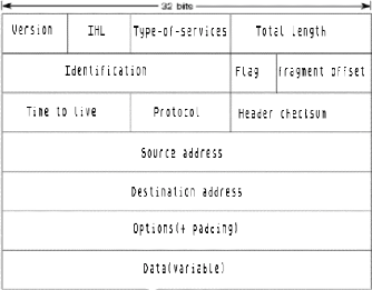
Figure 7: IP packet Datagram Source: Own
drawing
The following discussion describes the IP packet fields
illustrated in:
· Version--indicates the
version of IP currently used.
· IF Header Length
(IHL)--Indicates the datagram header length in 32-bit
words.
· Type-of-Service--Specifies how
an upper-layer protocol would like a current datagram to be handled, and
assigns datagrams various levels of importance.
· Total Length--specifies the
length, in bytes, of the entire IP packet, including the data and header.
· Identification--contains an
integer that identifies the current datagram. This field is used to help piece
together datagram fragments.
· Flags--consist of a 3-bit
field of which the two low-order (least-significant) bits control
fragmentation. The low-order bit specifies whether the packet can be
fragmented. The middle bit specifies whether the packet is the last fragment in
a series of fragmented packets. The third or high-order bit is not used.
· Fragment Offset--indicates
the position of the fragment's data relative to the beginning of the data in
the original datagram, which allows the destination IP process to properly
reconstruct the original datagram.
· Time-to-Live--maintains a
counter that gradually decrements down to zero, at which point the datagram is
discarded. This keeps packets from looping endlessly.
· Protocol--Indicates which
upper-layer protocol receives incoming packets after IP processing is
complete.
· Header Checksum--helps ensure
IP header integrity.
· Source
Address--specifies the sending node.
· Destination Address--specifies
the receiving node.
· Options--Allows IP to support
various options, such as security.
· Data--Contains upper-layer
information.
II.2.2.1.3 IP Addressing
As with any other network-layer protocol, the IP addressing
scheme is integral to the process of routing IP datagrams through an
internetwork. Each IP address has specific components and follows a basic
format. These IP addresses can be subdivided and used to create addresses for
subnetworks, as discussed in more detail later in this chapter.
Each host on a TCP/IP network is assigned a unique 32-bit
logical address that is divided into two main parts: the network number and the
host number. The network number identifies a network and must be assigned by
the InterNIC (Internet Network Information Center) if the network is to be part
ofthe Internet.
An ISP (Internet Service Provider) can obtain blocks of
network addresses from the InterNIC and can itself assign address space as
necessary. The host number identifies a host on a network and is assigned by
the local network administrator.
II.2.2.1.4 IP Address Format
The 32-bit IP address is grouped eight bits at a time,
separated by dots, and represented in decimal format (known as dotted decimal
notation). Each bit in the octet has a binary weight (128, 64, 32, 16, 8, 4, 2,
1). The minimum value for an octet is 0, and the maximum value for an octet is
255 Illustrates the basic format of an IP address.


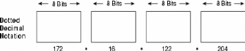
Figure 8: IP address consists of 32 bits, grouped into
four octets. Source:
http://www.cisco.com/univercd/cc/td/doc/cisintwk/ito_doc/ip.htm,September
24, 2006
II.2.2.2 UDP
UDP is a simple, datagram-oriented, transport layer protocol:
each output operation by a process produces exactly one UDP datagram, which
causes one IP datagram to be sent. This is different from a stream-oriented
protocol such as TCP where the amount of data written by an application may
have little relationship to what actually gets sent in a single IP datagram.
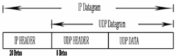
Figure 9: UDP encapsulation Source: Own
drawing
II.2.2.2.1 UDP Segment Structure
The UDP segment structure, shown in Figure 10
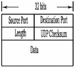
Figure 10: UDP segment structure
The application data occupies the data field of the UDP
datagram. For example, for DNS, the data field contains either a query message
or a response message. For a streaming audio application, audio samples fill
the data field. The UDP header has only four fields, each consisting of four
bytes.
As discussed in the previous section, the port numbers allow
the destination host to pass the application data to the correct process
running on that host (i.e., perform the demultiplexing function). The checksum
is used by the receiving host to check if errors have been introduced into the
segment during the course of its transmission from source to destination.
II.2.2.2.2 UDP Checksum
The UDP checksum covers the UDP header data. Recall that the
checksum in the IP header only covers the IP header; it does not cover any data
in the IP datagram. Both TCP and UDP have checksums in their headers to cover
their and their data. With UDP the checksum is optional, while it is
mandatory.
II.3 QUEUING DELAY AND JITTER BUFFER
II.3.1 BUFFER
A temporary storage area, usually in Random Access Memory
(RAM). The purpose of most buffers is to act as a holding area, enabling the
CPU to manipulate data before transferring it to a device.
Because the processes of reading and writing data to a disk
are relatively slow, many programs keep track of data changes in a buffer and
then copy the buffer to a disk. For example, word processors employ a buffer to
keep track of changes to files.
Then when file is saved, the word processor updates the disk
file with the contents of the buffer. This is much more efficient than
accessing the file on the disk each time change are made to the file.
Because changes are initially stored in a buffer, not on the
disk, all of them will be lost if the computer fails during an editing session.
For this reason, it is a good idea to save file periodically. Most word
processors automatically save files at regular intervals.
Buffers are commonly used when burning data onto a compact
disc, where the data is transferred to the buffer before being written to the
disc.
Another common use of buffers is for printing documents. When
entered a PRINT command, the operating system copies the document to a print
buffer (a free area in memory or on a disk) from which the printer can draw
characters at its own pace. This frees the computer to perform other tasks
while the printer is running in the background. Print buffering is called
spooling.
Most keyboard drivers also contain a buffer so that mistakes
can edit, typing before sending the command to a program. Many operating
systems, including DOS, also use a disk buffer to temporarily hold data that
they have read from a disk. The disk buffer is really a cache.12
II.3.2 JITTER BUFFER
Jitter buffers are used to counter "jitter"
introduced by packet networks so that a continuous playout of audio (or video)
transmitted over the network can be ensured. The maximum jitter that can be
countered by a de-j itter buffer is equal to the buffering delay introduced
before starting the play-out of the media stream.
Some systems use sophisticated delay-optimal jitter buffers
which are capable of adapting the buffering delay to changing network jitter
characteristics. These are known as adaptive de-j itter buffers and the
adaptation logic is based on the jitter estimates computed from the arrival
characteristics ofthe media packets.
Adaptive de-j ittering involves introducing discontinuities in
the media play-out which may
appear offensive to the listener / viewer.
Adaptive de-j ittering is usually carried out for audio
play-outs which
feature a VAD (Voice Activity Detection)/DTX (Discontinuous Transmission)
12
http://www.webopedia.com/TERM/b/buffer.html,September
12,2006
encoded audio, that allows the lengths of the silence periods
to be adjusted, thus minimizing the perceptual impact of the
adaptation.13
II.3.3 QUEUING DELAY
In computer engineering, a queuing delay is the
time a job waits in a queue until it can be executed.
This term is most often used in reference to routers. When
packets arrive at a router, they have to be processed and transmitted. A router
can only process one packet at a time. If packets arrive faster than the router
can process them (such as in a burst transmission) the router puts them into
the queue (also called the buffer) until it can get around to transmitting
them.
Queuing delay is proportional to buffer size. The longer the
line of packets waiting to be transmitted, the longer the average waiting time
is. However, this is much preferable to a shorter buffer, which would result in
ignored ("dropped") packets, which in turn would result in much longer overall
transmission times.14
II.3.4 LATENCY
In general, the period of time that one component in a system
is spinning its wheels waiting for another component. Latency, therefore, is
wasted time. For example, in accessing data on a disk, latency is defined as
the time it takes to position the proper sector under the read/write head.
In networking, the amount of time it takes a packet to travel
from source to destination. Together, latency and bandwidth define the speed
and capacity ofa network.
In VoIP terminology, latency refers to a delay in packet
delivery. VoIP latency is a service issue that is usually based on physical
distance, hops, or voice to data conversion. 15
13
http://en.wikipedia.org/wiki/Jitter_buffer#jitter_buffers,
September 24, 2006
14
http://en.wikipedia.org/wiki/Queueing_delay,
September 24,2006
15
http://serverwatch.webopedia.com/TERM/L/latency.html,January
24,2007
II.4 QUALITY of SERVICE II.4.1 INTRODUCTION
Quality of Service (QoS)
refers to the capability of a network to provide better service to
selected network traffic over various technologies, including Frame Relay,
Asynchronous Transfer Mode (ATM), Ethernet, Synchronous Optical Network
(SONET), and IP-routed networks that may use any or all ofthese underlying
technologies.
The primary goal of QoS is to provide priority including
dedicated bandwidth, controlled jitter and latency (required by some real-time
and interactive traffic), and improved loss characteristics.
Also important is making sure that providing priority for one
or more flows does not make other flows fail. QoS technologies provide the
elemental building blocks that will be used for future business applications in
campus, WAN and service provider networks.
II.4.2 QoS CONCEPTS
Fundamentally, QoS enabled to provide better service to
certain flows. This is done by either raising the priority of a flow or
limiting the priority of another flow. When using congestion- management tools,
it tryies to raise the priority of a flow by queuing and servicing queues in
different ways.
The queue management tool used for congestion avoidance
raises priority by dropping lowerpriority flows before higher-priority flows.
Policing and shaping provide priority to a flow by limiting the throughput of
other flows. Link efficiency tools limit large flows to show a preference for
small flows.
QoS tools can help alleviate most congestion problems.
However, many times there is just too much traffic for the bandwidth supplied.
In such cases, QoS is merely a bandage. A simple analogy comes from pouring
syrup into a bottle.
Syrup can be poured from one container into another container
at or below the size ofthe spout. If the amount poured is greater than the size
of the spout, syrup is wasted. However, it can use a funnel to catch syrup
pouring at a rate greater than the size of the spout. This allows to pour more
than what the spout can take, while still not wasting the syrup. However,
consistent over pouring will eventually fill and overflow the funnel.
II.4.3 BASIC QoS ARCHITECTURE
The basic architecture introduces the three fundamental pieces
for QoS implementation
· QoS identification and marking techniques for
coordinating QoS from end to end between network elements
· QoS within a single network element (for example,
queuing, scheduling, and trafficshaping tools)
· QoS policy, management, and accounting functions to
control and administer end-to-end traffic across a network
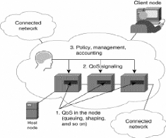
Figure 11: A Basic QoS Implementation Has Three Main
Components
Source:
http://www.cisco.com/univercd/cc/td/doc/cisintwk/ito_doc/qos.htm,september
24,2006
II.4.4 QoS WITHIN A SINGLE NETWORK ELEMENT
Congestion management, queue management, link efficiency, and
shaping/policing tools provide QoS within a single network element.
II.4.4.1 Congestion Management
Because of the bursty nature of voice/video/data traffic,
sometimes the amount of traffic exceeds the speed of a link. At this point,
some question has been asked, such as:
· What will the router do?
· Will it buffer traffic in a single queue and let the
first packet in be the first packet out?
· Or, will it put packets into different queues and service
certain queues more often?
Congestion-management tools address these questions. Tools
include priority queuing (PQ), custom queuing (CQ), weighted fair queuing
(WFQ), and class-based weighted fair queuing (CBWFQ).
II.4.4.2 Queue Management
Because queues are not of infinite size, they can fill and
overflow. When a queue is full, any additional packets cannot get into the
queue and will be dropped. This is a tail drop. The issue with tail drops is
that the router cannot prevent this packet from being dropped (even if it is a
high-priority packet). So, a mechanism is necessary to do two things:
1. Try to make sure that the queue does not fill up, so that
there is room for high-priority packets
2. Allow some sort of criteria for dropping packets that are
of lower priority before dropping higher-priority packets Weighted early random
detect (WRED) provides both of these mechanisms.16
16
http://www.cisco.com/univercd/cc/td/doc/cisintwk/ito_doc/qos.htm,
September 24, 2006
II.5 MULTIMEDIA OVER IP
In this point let talk more about the following protocols:
> Resource ReServVation Protocol (RSVP) > Real-Time
Transport Protocol (RTP)
> Real-Time Control Protocol (RTCP)
> Real-Time Streaming Protocol (RTSP)
Which are the foundations ofreal-time services. II.5.3.1
RSVP (Resource ReSerVation Protocol)
RSVP is used to set up reservations for network resources.
When an application in a host (the data stream receiver) requests a specific
quality of service (QoS) for its data stream, it uses RSVP to deliver its
request to routers along the data stream paths. RSVP is responsible for the
negotiation of connection parameters with these routers. If the reservation is
setup, RSVP is also responsible for maintaining router and host states to
provide the requested service. Each node capable of resource reservation has
several local procedures for reservation setup and enforcement
II.5.3.2 RTP (Real-time Transport Protocol)
Realtime transport protocol (RTP) is an IP-based protocol
providing support for the transport of real-time data such as video and audio
streams. The services provided by RTP include time reconstruction, loss
detection, security and content identification.
RTP is primarily designed for multicast of real-time data, but
it can be also used in unicast. It can be used for one-way transport such as
video-on-demand as well as interactive services such as Internet telephony.
II.5.3.3 RTCP (Real-Time Control Protocol)
RTCP is the control protocol designed to work in conjunction
with RTP.In an RTP session, participants periodically send RTCP packets to
convey feedback on quality of data delivery and information of membership.
There are five RTCP packet types to carry control information. These five types
are:
> Receiver Report (RRe): Receiver reports
are generated by participants that are not active senders. They contain
reception quality feedback about data delivery, including the highest packets
number received, the number of packets lost, inter-arrival jitter, and
timestamps to calculate the round-trip delay between the sender and the
receiver.
> Sender Report (SR): Sender reports are
generated by active senders. In addition to the reception quality feedback as
in RR, they contain a sender information section, providing information on
inter-media synchronization, cumulative packet counters, and number of bytes
sent.
> Source description items (SDES): They
contain information to describe the sources. > BYE:
indicates end of participation.
> APP: application specific functions. It is
now intended for experimental use as new applications and new features are
developed.
II.5.3.4 Real-Time Streaming Protocol (RTSP)
Instead of storing large multimedia files and playing back,
multimedia data is usually sent across the network in streams. Streaming breaks
data into packets with size suitable for transmission between the servers and
clients.
The real-time data flows through the transmission,
decompressing and playing back pipeline just like a water stream. A client can
play the first packet; decompress the second, while receiving the third. Thus
the user can start enjoying the multimedia without waiting to the end of
transmission.
RTSP, the Real Time Streaming Protocol, is a client-server
multimedia presentation protocol to enable controlled delivery of streamed
multimedia data over IP network. It provides "VCR-style" remote control
functionality for audio and video streams, like pause, fast forward, reverse,
and absolute positioning. Sources of data include both live data feeds and
stored clips.
RTSP is an application-level protocol designed to work with
lower-level protocols like RTP, RSVP to provide a complete streaming service
over internet. It provides means for choosing delivery channels (such as UDP,
multicast UDP and TCP), and delivery mechanisms based upon RTP. It works for
large audience multicast as well as single-viewer unicast.
> MULTIMEDIA NETWORKING
Multimedia can roughly be defined as a technology that enables
humans to use computers capable of processing textual data, audio and video,
still pictures, and animation. Applications range over entertainment,
education, information provision; design e.g. CAD/CAM, co-operative working
such as video conferencing, application sharing, remote working and virtual
reality experiences.
Multimedia applications for computers have been developed for
single computing platforms such as the PC, Apple Mac and games machines. The
importance of communications or networking for multimedia lies in the new
applications that will be generated by adding networking capabilities to
multimedia computers, and hopefully gains in efficiency and cost of ownership
and use when multimedia resources are part of distributed computing systems.
Widening of access to multimedia sources and potential markets in multimedia,
video and information are commercial driving force for networking
multimedia.
The reality of networking multimedia is that, the
characteristics of multimedia make heavy demands on storage and transmission
systems. Data compression can be used to reduce the demands of multimedia,
particularly of video and audio on these systems, but usually at the expense of
some loss in the detail compared with the source and at extra cost.
The ways in which users or participants in multimedia sessions
access multimedia or connect with others have important consequences for the
storage and transmission systems. For instance multimedia learning material can
be accessed directly from a server during a class or downloaded to student
machines prior to a session. The demands on a connecting network are very
different in each access mode.
The cost of transmitting multimedia information will determine
the pace of development of networked multimedia applications. The availability
of standards for multimedia networking, particularly for inter-working between
applications, the development of networked applications, and interworking
between networks are essential to reduce the complexity and level of skill
required in using multimedia.
II.5.1.1 USER REQUIREMENTS FOR MULTIMEDIA II.5.1.1.1
Computer Interface
The standards of reproduction for computers which are
desirable have been set by the publishers of books, music, Walt Disney cartoons
and television producers. With the development of High Definition TV and
beyond, it is likely that there will be a continual increase in the demands
placed on computer based multimedia systems.
The current PAL standard in the UK delivers video in 625 lines
at 25 frames/sec. High Definition TV delivers video in 1250 lines with a higher
horizontal resolution at 25 frames/sec and requires about five times the
information rate as the current PAL system.
Multimedia applications like any other application, appliance
or tool, benefit from being easy to use, with minimal training or self
learning. The need for a well designed human - computer interface, which may be
screen or audio based is well accepted.
II.5.1.1.2 Access, Delivery, Scheduling and
Recording
Alternatively the delivery of information at a later time is
acceptable if it can be scheduled, as in a TV broadcast schedule, or a first
class postal letter. Scheduling the delivery of multimedia information has not
been widely implemented. Scheduling can have advantages for users over on
demand delivery. In a learning situation times can be defined for class
attendance by a lecturer. In open learning situations learners can control
their programme by requesting a multimedia unit at a convenient time.
Just as we can record a TV film on a VHS recorder, some
multimedia computer users will wish to record a film, session, or learning
experience for future reference.
II.5.1.2 CHARACTERISTICS OF MULTIMEDIA
Multimedia can be as simple as a few images with some
accompanying text to a multimedia presentation using video clips, sound, images
animation and text. Multimedia files to use a lot of data when in a digital
format. Video is the most demanding. A PAL signal when digitised can require a
data rate of 170 Mbps. Audio is less demanding but still requires 1.3 MB for a
1 minute clip using a Sound Blaster Pro system at 22 kHz sampling rate. Still
images require use more data proportional to their size. Synchronisation of
sound and video is important. Sound is likely to break up if parts of it are
lost or delayed in storage or transmission.
Video is less vulnerable to loss (depending on the
application), but still requires the entire picture to be on the screen at the
same time and is also vulnerable to jitter. Jitter could be controlled in some
applications if the sender of the isochronous video data time stamps each piece
of data when it is generated, using a universal time source, and then sends the
data to the receiver. The receiver reads a piece of data in as soon as it is
received and store it. The receiver processes each piece of data only at the
time equal to the data's time stamp plus the maximum transit delay. Thus
isochronised of the video would be restored.
II.5.1.2 COMPRESSION
have this sort of network access compression is the only hope for
the widespread deployment of digital video and multimedia.
Compression techniques depend on algorithms implemented in
software or hardware. The use of hardware is important still to enable rapid
compression, and also speeds de- compression. At this time the cost of hardware
is still high, from 200 to 350 for a MPEG video compression PC card. Sound
cards can implement proprietary compression, and software only video
compression is available in products like Microsoft Video for Windows, or for
UNIX operating system workstations.
While compression can ease the demands on networks and storage
media there is several trades-offs. Since some compression techniques remove
information considered to be less important a loss in resolution may result.
Once material is compressed the algorithms may prevent access to single frames
of video for viewing or editing. The cost of complex hardware and software and
compression and decompression delay are other factors important to users.
Different uses require different compression methods. Video
conferencing must be done in real time so fast encoding and decoding is needed.
This is the aim of the H.261 standard. Video film distribution via cable
networks, radio or CD is essentially a playback process, so encoding is not
time critical, and decoding should be easy to implement to reduce consumer
costs. The MPEG standards address these applications.
MIDI encoding of audio notes is not really a compression
method, but almost another form of media. Inevitably, successful compression
techniques encourage the design of applications which require higher bandwidths
still, such as Super Definition TV which will also require appropriate
compression.
II.6 STREAMING PROCESS II.6.1 STREAMING
A technique for transferring data such that it can be
processed as a steady and continuous stream. Streaming technologies are
becoming increasingly important with the growth of the Internet because most
users do not have fast enough access to download large multimedia files
quickly. With streaming, the client browser or plug-in can start displaying the
data before the entire file has been transmitted.
For streaming to work, the client side receiving the data must
be able to collect the data and send it as a steady stream to the application
that is processing the data and converting it to sound or pictures.
This means that if the streaming client receives the data more
quickly than required, it needs to save the excess data in a buffer. If the
data doesn't come quickly enough, however, the presentation ofthe data will not
be smooth.
There are a number of competing streaming technologies
emerging. For audio data on the Internet, the de facto standard is Progressive
Network's RealAudio. 17
II.6.2 UNICAST
In computer networks, unicast is the sending of information
packets to a single destination. "Unicast" is derived from the word broadcast,
as unicast is the extreme opposite of broadcasting. In computer networking,
multicasting is used to regain some of the efficiencies ofbroadcasting. These
terms are also synonymous with streaming content providers' services. Unicast
servers provide a stream to a single user at a time, while multicast servers
can support a larger audience by serving content simultaneously to multiple
users.18
17
www.webopedia.com/TERM/M/streaming.htm,friday,novembre
17,2006
18
http://en.wikipedia.org/wiki/Unicast,friday,novembre
17,2006
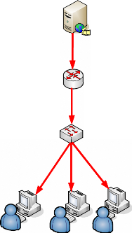
II.6.2.1 UNICAST ARCHITECTURE
Unicasts transmits separate video, audio or text streams to each
computer requesting data. Unicast video can flood the network.
STREAMING
SERVER
ROUTER
SWITCH
LEGEND
|
TO CLIENT 1
TO CLIENT2
TO CLIENT3
|
CLIENT 1CLIENT 2 CLIENT 3
Figure 12 : High Level Network diagram for
UNICAST Source: Own drawing
II.6.3 MULTICAST
destinations simultaneously using the most efficient strategy to
deliver the messages over each link ofthe network only once and only create
copies when the links to the destinations split.
The word "Multicast" is typically used to refer to IP
Multicast, the implementation of the multicast concept on the IP routing level,
where routers create optimal spanning tree distribution paths for diagrams sent
to a multicast destination address in real-time.
II.6.3.1 MULTICAST ARCHITECTURE
STREAMING
SERVER
ROUTER
SWITCH
Multicast conserves Network bandwidth by sending a single stream
of data.
LEGEND
CLIENTCLIENT
CLIENT
Figure 13 : High Level Network for MULTICAST
II.6.4 BROADCAST
To simultaneously send the same message to multiple
recipients. Broadcasting is a useful feature in e-mail systems. It is also
supported by some fax systems. In networking, a distinction is made between
broadcasting and multicasting. Broadcasting sends a message to everyone on the
network whereas multicasting sends a message to a select list ofrecipients.
II.6.4.1 BROADCAST TECHNIQUE OF IP PACKET
MODEL
As known, broadcast is when a single device is transmitting a
message to all other devices in a given address range. This broadcast could
reach all hosts on the subnet, all subnets, or all hosts on all subnets.
Broadcast packets have the host (and/or subnet) portion of the
address set to all ones. By design, most modern routers will block IP broadcast
traffic and restrict it to the local subnet.
And multicast is a special protocol for use with IP. Multicast
enables a single device to communicate with a specific set of hosts, not
defined by any standard IP address and mask combination. This allows for
communication that resembles a conference call.
Anyone from anywhere can join the conference, and everyone at
the conference hears what the speaker has to say. The speaker's message isn't
broadcasted everywhere, but only to those in the conference call itself. A
special set of addresses is used for multicast communication. In this case the
IP that has been used for multicast and broadcast is the same, and it is
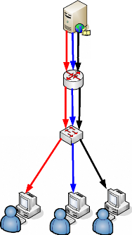
192.168.12.2 which can be reachable by all users inside the network.
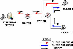
Figure 14: Broadcasting process Source: Own
drawing
To decrease traffic inside the network, broadcast has been
used as it is the way that can help during live video streaming. The above
figure show the broadcast process, the colored in red arrow shown the request
of packets to the server from the CLIENT 1 that got the reply shown with black
arrow.
The blue arrow shows the request of the CLIENT 2 to the CLIENT
1 which got packets before CLIENT 2 instead of getting packets from the server.
Broadcast process could help to maintain the performance and the quick relay of
multimedia services inside networks.
II.6.5 HIGH LEVEL NETWORK ARCHITECTURE
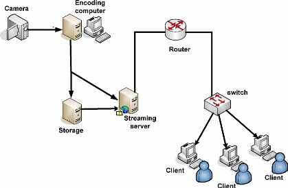
Figure 15: High level Network Architecture of live video
streaming Source: Own Drawing
The figure above shows all requirements of a live video streaming
that are follow:
· A camera for capturing video
· An encoding machine to encode video file into a
compatible format for streaming
· A storage machine for storing files that has been got on
demand
· A streaming server that can stream both stored file and
live files.
· A router and a Switch
· Clients Machines
II.7 MULTIMEDIA APPLICATIONS
In networking, there are many applications used wired media that
are following:
> Streaming video > Streaming audio >
Collaboration
> One-way and interactive multimedia messaging
> Gaming, including interactive peer-to-peer (p2p) gaming
> Digital money transactions
> MP319 music download
> Video- and audio-supported shopping
> Long-distance learning, education
> Video and audio conferencing
> File sharing and transfer (pictures, video clips, and
text)
> Feeding of real-time news and information about the weather,
financial markets, sports and so on
> Geographic location services
> Safety services > Gambling
> Entertainment
But in this project, the focused application is video
streaming.
Let define HiperLAN, which is HiperLAN is a set of wireless
local area network (WLAN) communication standards primarily used in European
countries. There are two specifications: HiperLAN/1 and HiperLAN/2. Both have
been adopted by the ETSI (European Telecommunications Standards Institute).
19 MP3 is the Compression scheme used to transfer audio files via
the Internet
II.7.1 VIDEO AND AUDIO STREAMING
Video and audio streaming provides the means of delivering
news, entertainment, remote education, documentary, corporate speeches, fashion
shows, and many more types of communication. Television may be the most
well-known form of streaming video. It already feeds wireless multimedia
streams into millions of dishes and antennas, connected to TVs and other
devices. DirecTV and Dish Networks are two major providers of streaming video
in the United State.
Streaming technologies are important, since most users do not
have access to enough connection capacity to download large multimedia files
quickly. Using streaming technologies, consumers can start listening to the
audio stream or view the video stream before the entire file has been
received.
To allow efficient streaming, the provider needs to send the
data as a steady stream and the receiver needs to be able to cache excess data
in a temporary buffer until used. If the data do not arrive fast enough, users
will experience interruptions. There are several competing streaming
technologies, such as RealAudio player, RealVideo player, Microsoft Media
Player, PacketVideo player, and QuickTime player.
To reduce the amount of information transmitted, streaming
video and audio data are compressed by means of technologies such as MPEG. The
streaming video quality depends on the capacity of the transmission channel and
its ability to support a steady stream the better the channel quality (i.e.,
higher and steady data rate), the better the quality ofthe audio and video
output.20
20 Aura Ganz, Zvi Ganz, Kitti Wongthavarawat, Multimedia
Wireless Networks: Technologies, Standards, and QoS, Prentice Hall, page
12,13
II.7.2 PACKETS SCHEDULING
The packet scheduling algorithm
1) Allocates bandwidth for connections in terms ofthe number
ofpackets and
2) Determines when a connection is allowed to transmit. The
packet scheduling algorithm uses the RR and RG. The standard does not define
the packet scheduling algorithm. Itjust defines the signaling mechanism such as
RR and RG.21
Figure 16 summarizes the HiperLAN/2 QoS architecture which
provides the necessary mechanisms to deliver per-flow quantitative QoS
services.
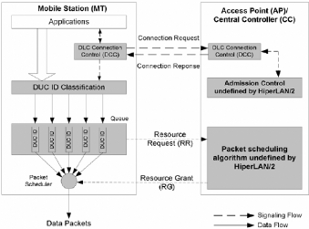
Figure 16: HiperLAN/2 QoS
Architecture
Source: Aura Ganz, Zvi Ganz, Kitti Wongthavarawat, Multimedia
Wireless Networks: Technologies, Standards, and QoS, Prentice Hall
21 Aura Ganz, Zvi Ganz, Kitti Wongthavarawat, Multimedia
Wireless Networks: Technologies, Standards, and QoS, Prentice Hall, page
110
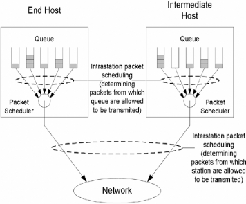
II.7.3 PACKETS SCHEDULING MECHANISM
Packet scheduling is the mechanism that selects a packet for
transmission from the packets waiting in the transmission queue. It decides
which packet from which queue and station are scheduled for transmission in a
certain period of time. Packet scheduling controls bandwidth allocation to
stations, classes, and applications.
As shown in Figure 17, there are two levels ofpacket scheduling
mechanisms:
1. Intrastation packet scheduling: The packet scheduling
mechanism that retrieves a packet from a queue within the same host.
2. Interstation packet scheduling: The packet scheduling
mechanism that retrieves a packet from a queue from different hosts.
Figure 17: Packet Scheduling
Packet scheduling can be implemented using hierarchical or flat
approaches.
> Hierarchical packet scheduling: Bandwidth is allocated to
stations--that is, each station is allowed to transmit at a certain period of
time. The amount of bandwidth assigned to each station is controlled by
interstation policy and module. When a station receives the opportunity to
transmit, the intrastation packet scheduling module will decide which packets
to transmit.
> This approach is scalable because interstation packet
scheduling maintains the state by station (not by connection or application).
Overall bandwidth is allocated based on stations (in fact, they can be groups,
departments, or companies). Then, stations will have the authority to manage or
allocate their own bandwidth portion to applications or classes within the
host.
> Flat packet scheduling: Packet scheduling is based on all
queues of all stations. Each queue receives individual service from the
network.
Packet scheduling mechanism deals with how to retrieve packets
from queues, which is quite similar to a queuing mechanism. Since in
intrastation packet scheduling the status of each queue in a station is known,
the intrastation packet scheduling mechanism is virtually identical to a
queuing mechanism.Interstation packet scheduling mechanism is slightly
different from a queuing mechanism because queues are distributed among hosts
and there is no central knowledge of the status of each queue. Therefore, some
interstation packet scheduling mechanisms require a signaling procedure to
coordinate the scheduling among hosts.
Because of the similarities between packet scheduling and
queuing mechanisms ,there is introduction of a number of queuing schemes (First
In First Out [FIFO], Strict Priority, and Weight Fair Queue [WFQ]) and briefly
discuss how they support QoS services.22
22 Aura Ganz, Zvi Ganz, Kitti Wongthavarawat, Multimedia
Wireless Networks: Technologies, Standards, and QoS, Prentice Hall, page
56,57
CHAPTER III: RESEARCH METHODOLOGYAND ANALYSIS OF
MULTIMEDIA SERVICES
III.1 Introduction
A methodology is a series of choices such us choices about
what information and data to gather, Choices about how to analyze the
information and data that you gather and other methodological choices. In This
project the choice made is the one that helped to analyze the network by making
comparison and it is called a comparative research methodology.
Comparative methodology is the act of comparing two or more
things with a view to discovering something about one or all of the things
being compared. This technique often utilizes multiple disciplines in one
study.
When it comes to method, the majority agreement is that there
is no methodology peculiar to comparative research. The multidisciplinary
approach is good for the flexibility it offers, yet comparative programs do
have a case to answer against the call that their research lacks a
«seamless whole». 23In this case the comparison was done
between traditional streaming and IP packet charging models in a network.
III.2 Section approach
This section presents a methodology evaluation framework
within which the methodology comparison is conducted. This framework consists
of a series of questions used to identify and quantify a methodology's support
for a specific development process. The framework employed considers four major
areas ofeach methodology:
· Concepts
· Notations
· Process
· Pragmatics
23
http://en.wikipedia.org/wiki/Comparative_research,September
24, 2006
III.2.1 Concepts
This section cites from the particular method and then
contrasts support for terms within each method under scrutiny i.e. this section
is the theoretical concepts that have been used in this work.
III.2.2 Notations
Many methods require the creating of abstract descriptions,
or graphical models, of the system under analysis and/or design. In this study,
the system under analysis are traditional streaming and IP packet charging
model for multimedia services i.e. result that has been found by testing the
network performance and quick relay of both traditional streaming and IP packet
charging model for multimedia services have been compared in order to get the
advantages and disadvantages of the above systems
III.2.3 Process
The process component of this comparison is used to
characterize within what development contexts the method is appropriate, how
much of the systems analysis is covered by the methodology used.
III.2.4 Pragmatics
This section considers the pragmatics ofthe methodology. A
methodology's pragmatics consists of:
· Resources
· Required Expertise
· Accessibility
· Domain Applicability
III.3 Live media model Analysis
This part of the project focuses on making comparison between
traditional live streaming and packets charging model for multimedia services.
When comparing both traditional live streaming and packets charging model for
multimedia services, there are some factors that will be take in consideration
such as bandwidth, latency, jitter and so on.
After doing comparison, the comparison table between
traditional live streaming and packets charging model will e needed in order to
show the differences between them according their behavior inside the
network.
III.3.1 TRADITIONNAL STREAMING
The traditional streaming has been done by using streaming
technologie used before by Microsoft; In this case some tools have been taken
in consideration such as:
· A computer network.
· A video file with 360 Kbs that has been taken as
sample.
· A web server that helped to stream the file above
· And Iris Network Analyzer for analyzing network
performance and quick relay of multimedia services in general and a video file
in our case.
· Three computers; the first one worked as server and the
other two as client.
III. 3.1.1 HIGHLEVEL NETWORK DIA GRAM FOR TRADITIONNAL
STREAMING
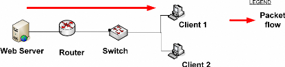
In traditional streaming, video file has been posted into the
web server on which the client makes access to the server by using the hyper
text transfer protocol (http).
III. 3.1.2 NETWORK PERFOMANCE RESULT
After testing the latency of traditional streaming, the results
got are as follow:
As mentioned, the file used has 360 Kbs of size. The traffic of
packets started at 22:16:26 and ended at 22:16:39.
Hours
|
Packets/Sec
|
22:16:26
|
0
|
22:16:27
|
2
|
22:16:28
|
4
|
22:16:29
|
12
|
22:16:30
|
2152
|
22:16:31
|
1885
|
22:16:32
|
3084
|
22:16:33
|
2666
|
22:16:34
|
3597
|
22:16:35
|
1708
|
22:16:36
|
4
|
22:16:37
|
6
|
22:16:38
|
7
|
22:16:39
|
0
|
|
Table 1: Bandwidth test for traditional streaming
Source: Own Result
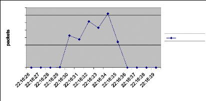
4000
2500
2000
3500
3000
1500
1000
500
0
hours
Packets/Sec
Figure 19: Bandwidth diagram for traditional streaming
Source: Own Result
During traditional streaming the number of packets is
occupying the bandwidth and it is varying between 0 and 4000 packets per second
which show that there has been a big number ofpackets in traffic.
III. 3.1.2 THE REAL-TIME CHALLENGE
Multimedia networking is not a trivial task. We can expect at
least three difficulties.
First, compared with traditional textual applications,
multimedia applications usually require much higher bandwidth. A typical piece
of 25 second 320x24 movies could take about 2.3MB, which is equivalent to about
1000 screens of textual data. This is unimaginable in the old days when only
textual data is transmitted on the net.
Second, most multimedia applications require the real-time
traffic. Audio and video data must be played back continuously at the rate they
are sampled.
If the data does not arrive in time, the playing back process
will stop and human ears and eyes can easily pick up the artifact. In Internet
telephony, human beings can tolerate a latency of about 250 milliseconds.
If the latency exceeds this limit, the voice will sound like
a call routed over a long satellite circuit and users will complain about the
quality ofthe call. In addition to the delay, network congestion also has more
serious effects on real-time traffic.
If the network is congested, the only effect on non-realtime
traffic is that the transfer takes longer to complete, but real-time data
becomes absolute and will be dropped if it doesn't arrive in time. If no proper
reaction is not taken, the retransmission of lost packets would aggravate the
situation andjam the network.
Third, multimedia data stream is usually bursty. Just
increasing the bandwidth will not solve the burstiness problem. For most
multimedia applications, the receiver has a limited buffer. If no measure is
taken to smooth the data stream, it may overflow or underflow the application
buffer.
When data arrives too fast, the buffer will overflow and the
some data packets will be lost, resulting in poor quality. When data arrives
too slowly, the buffer will underflow and the application will starve.
Contrary to the high bandwidth, real-time and bursty traffic
of multimedia data, in real life, networks are shared by thousands and millions
of users, and have limited bandwidth, unpredictable delay and availability. How
to solve these conflicts is a challenge multimedia networking must face.
The possibility of answering this challenge comes from the
existing network software architecture and fast developing hardware. The basis
of Internet, TCP/IP and UDP/IP, provides a range of services that multimedia
applications can use.
Fast networks like Gigabit Ethernet, FDDI, and ATM provide
high bandwidth required by digital audio and video. So the design of real-time
protocols for multimedia networking becomes imperative before the multimedia
age comes.
CHAPTER IV: ANALYSIS AND IMPLEMENTATION OF LIVE VIDEO
STREAMING
IV.1 Introduction
In this project, In order to show how IP packets charging
model for multimedia services inside the network, live video streaming has been
taken as one of application that can explain how packets charging model.
To stream a file there are some requirement that are needed,
such us an encoder, a server and the relay software24. In this
study, requirements used are Nullsoft technology.
To start live streaming using nullsoft technology, the following
tools are required:
· A computer network
· A shoutcast server
· NSV tools (NullSoft Video tools) which help to capture
and decode file
· Winamp for the client
For hardware, tools needed are the following:
· A web Camera (webcam)
· Computers
· A router
· A Switch
IV.4.1 HARDWARE SPECIFICATION
To achieve goals given before, PCs of 256 RAM and 2.80 GHz
ofprocessor are needed, in this project three PCs has been used in the network
.The first one worked as a streaming server and the last two worked as
clients.
24 Relay software is the software which helps clients to
communicate with the server.
PCs SPECIFICATION TABLE
PC NAME
PC Specification
|
SERVER
|
CLIENT 1
|
CLIENT 2
|
RAM
|
256 MB
|
256MB
|
256MB
|
Processor
|
2.80 GHz
|
2.80 GHz
|
2.80 GHz
|
IP
|
192.168.12.2
|
192.168.10.2
|
192.168.10.3
|
|
Table 2: PCs specification Source: Own
result
PCs CONNECTION DIAGRAM
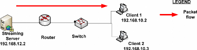
Figure 20: PCs connection diagram Source: Own
drawing
IV.2 Shoutcast configuration
To get connection between server and client, server must be
configured; in this case shoutcast has been configured as server.
IV.2.1 START SHOUTCAST CONFIGURATION
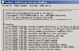
Figure 21 : Start shoutcast server
Source:
http://www.scvi.net/shoutcast.htm,january
27, 2007
After starting the server The following Warning box open
IV.2.2 WARNING CONFIGURATION
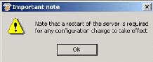
Figure 22: Configuration warning
Source:
http://www.scvi.net/shoutcast.htm,
January 27, 2007
IV.2.3 SHOUTCAST CONFIGURATION FILE
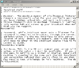
Figure 23: Shoutcast configuration file
Source:
http://www.scvi.net/shoutcast.htm,
January 27, 2007
In this document the requirement change are as follow:
· Shoutcast password that is set by default as
«change»(It is highly recommended to note the password down for
future reference, and that password is helping in later steps)
· MaxUser count (In order to support a quality video
stream), the administrator could get a limit number of user.
IV.3 live video streaming using nsv
capture
The first thing to do is to source (send) the video to a
shoutcast compatible server to be streamed. To start the process of capturing
video, the set capture destination must be selected
IV.3.1 SET CAPTURE DESTINATION
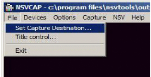
Figure 24: NSV tools configuration to set capture
destination Source:
http://www.scvi.net/liveenc.htm,
january 27,2007
The above Figure show where to click for getting the file
configuration ofNSV capture.
IV.3.2 SET CAPTURE DESTINATION FILE The
configuration ofthe capture destination option
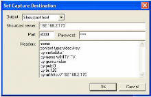
Figure 25: Set capture destination
Source:
http://www.scvi.net/liveenc.htm,
january 27,2007
Output: Set to Shoutcast server
1. Shoutcast server: Enter the Shoutcast server IP(if it is a
local Shoutcast running on the local machine the 127.0.0.1 IP address is
required for local loopback)
2. Port: Enter the port you intend on streaming the NSV output
to the Shoutcast server on
3. Password: Enter the password used for the shoutcast server
4. The headers: Memo -password
content-type: video/nsv - it can't be changed
icy-metadata: 1
icy-name: WHITY TV - your station name
icy-genre: video - type of genre
icy-pub: 0E- publicly listed on Winamp TV directory icy-br: 128E-
Estimated bitrate
icy-url:http://1 92.168.2.170E- it can't be changed
IV.3.3 NVS tools FOR DE VICES
The following step is the selection of devices required for video
and audio
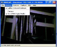
Figure 26: NVS tools for capturing cards
Source:
http://www.scvi.net/liveenc.htm,
January 27, 2007
IV.3.4 SET CAPTURE DESTINATION
Many capture cards have selections for composite, SVideo, or
TV tuner, which must be configured according to the device connected. In this
case the above options are disabled because ofusing a webcam.
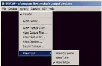
Figure 27: Selection of video input
Source:
http://www.scvi.net/liveenc.htm,
January 27,2007
The following step is the selection of Video standard and
picture adjustment.
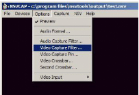
Figure 28: Video capture filter configuration
Source:
http://www.scvi.net/liveenc.htm,
January 27,2007
IV.3.5 VIDEO DECODER CONFIGURATION
In order to get video format that is compatible with the
shoutcast, the Video standard must be as follows:
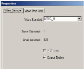
Figure 29: Video Decoder configuration
Source:
http://www.scvi.net/liveenc.htm,
january27,2007
And any picture adjustment is done in this configuration
window:
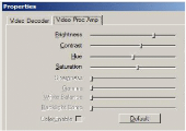
Figure 30: Video Proc Amp
Source:
http://www.scvi.net/liveenc.htmjanuary
27, 2007
IV.3.6 VIDEO CAPTURING PIN CONFIGURATION
The following step is to set the device compress and set
resolution to 320x240 for streaming, which is the preferred order of choice for
the video codec. The following are some Video Format Preference:
· I420 or YV12 which is the best choice
· YUY2 or UYVY which is better than RGB24
· RGB24 or RGB32 which is used as last ressort
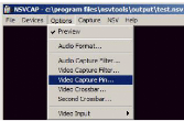
Figure 31: Video Capture pin Source: Own
result
IV.3.7 VIDEO CAPTURING CONFIGURATION
The other Video Format Preference that is listed may not work
at all. This depends on whether or no the encoding tool can handle the
conversion. The following option allows the capture of audio with the video and
allows sound to be included in the video.
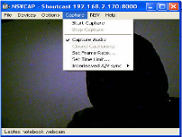
Figure 32: Video capture configuration Source:
Own result
To configure the encoder there are several steps such as:
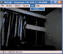
Figure 33: NSV configuration Source: Own
result
The `top' and `bottom' labels in this window are reversed.
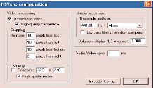
Figure 34: NSV encoder configuration Source: Own
result
Video: Deinterlance with high quality for all
«video outs» from other machines as NTSC is 512 lines interlaced.
Webcam's direct screen captures are not interlaced. But some movies are
interlaced and may need this enabled as well.
Cropping: If the capture output does not fill
the screen. There must be the configuration of pixels that must fit the
screen.
To run the server, the option captured helped to enable NSVcap to
start capturing images.
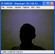
Figure 35: The first image to send to the client
Source: Own result
The following figure, show how to start capturing the image.
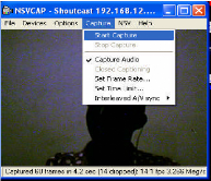
Figure 36: starting capturing the image Source:
Own result
The choice of Shoutcast as server is because it can stream
faster, and it has been adapted to Real time streaming protocols.
After all the above steps, the client will be able to watch in
live the image captured.
IV.4 Results analysis
IV.4.1 LATENCY
After carrying out the live video streaming, it is very
important to test the latency time. The test during this research has been done
in three different days in three different times, i.e. the morning, the day and
the evening. Latency has been defined as the period of time that one component
in a system is spinning its wheels waiting for another component; it is the
reason why the table below showed how latency has been calculated during
experiences by following images motions.
The following table show the latency tested according to the
motion of a gesture during the live video streaming seen on the streaming
server and client 1.
|
DAYS TIME
|
1st day
|
2nd day
|
3rd day
|
Average
|
|
Morning
08:00 to 10:00
|
06 secs
|
10 secs
|
09 secs
|
8.3 secs
|
|
Day
12:00to 14:00
|
12 secs
|
11 secs
|
12 secs
|
11.6 secs
|
|
Night
18:00 to 20:00
|
08 secs
|
07 secs
|
07 secs
|
7.3 secs
|
|
Average
|
08.66 secs
|
09.3 secs
|
09.3 secs
|
09.06 secs
|
Table 3: latency test Source: Own Result
As shown in the above table, the latency in Packets charging
model is not great that to show that there is a high performance and quick
relay of live video.
IV.4.2 BANDWIDTH
In computer networks, bandwidth is often used as a synonym for
data transfer rate the amount of data that can be carried from one point to
another in a given time period.
In this project, Number of packets per second helped to test
network performance. Number of packets per second. Almost the same amount of
processing needs to be done on a packet with 1500 byte payload as for a packet
with a one byte payload. The number of packets per second determines the number
of times the state table and, in case of no match there, filter rules have to
be evaluated every second, determining the effective demand on the system.
(a) Intrastation packets scheduling (When starting to
send data local host)
This case is Intrastation packet scheduling which follow the
mechanism that retrieves a packet from a queue within the same host which has
the following IP address 192.168.12.2
|
192.168.12.2
|
|
Hours
|
Packets/sec
|
|
22:09:55
|
0
|
|
22:09:56
|
6
|
|
22:09:57
|
4
|
|
22:09:58
|
9
|
|
22:09:59
|
7
|
|
22:10:00
|
6
|
|
22:10:01
|
9
|
Table 4: Intrastation packets scheduling Source:
Own Result
Diagram
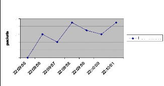
10
4
8
6
2
0
Intrastation packets scheduling
Hours
Packets/sec
Figure 37: Intrastation packets scheduling
Source: Own drawing
The diagram shown above is explaining the behavior of packets
during the intrastation packets scheduling inside the network, the number of
packets inside the network increase in function of time, and it is varying
between 0 and 10. As known, Intrastation packet scheduling is the packet
scheduling mechanism that retrieves a packet from a queue within the same host;
it is the reason why the packets traffic is varying between 0 and 10 packets
per second.
(b) The Interstation packet scheduling
This case is the Interstation packet scheduling which follow the
mechanism that retrieves a packet from a queue from different hosts.
|
IP Hours
|
192.168.10.2 Packets/Sec
|
192.168.10.3 Packets/Sec
|
|
22:26:38
|
7
|
8
|
|
22:26:40
|
5
|
6
|
|
22:26:42
|
7
|
7
|
|
22:26:44
|
5
|
4
|
|
22:26:46
|
3
|
4
|
|
22:26:48
|
3
|
5
|
|
22:26:50
|
21
|
24
|
|
22:26:52
|
17
|
12
|
Table 5: Interstation packets scheduling:
Source: Own result
The above table can be shown in the following diagram which
showed packets variation inside the network for two clients that are connected
to the server. As said before, Interstation packet scheduling is packet
scheduling mechanism that retrieves a packet from a queue from different hosts
that can cause the augmentation of packets traffic inside the network. In this
case packets traffic per second varies between 0 and 35.
Diagram
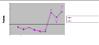
25
20
30
15
10
5
0
1 2 3 4 5 6 7 8 9 10
Hours
192.168.10.2 Packets/Sec
192.168.10.3 Packets/Sec
Figure 38: Interstation packets scheduling
Source: Own drawing
According to the above results, there can be a comparison with
traditional streaming, as shown in the table 1, packets are Varying between 0
and 4000 packets per second, then by comparing those result with those of
packets charging model the can be a big difference because the variation
ofpackets during packet charging is very small and it is varying between 0 and
35.
The following table shows the difference between traditional
streaming and packets charging model; and it has been shown in the following
comparative table between Traditional streaming and Packet charging model.
|
Model of streaming
Hours
|
Traditionnal Streaming Packets/Sec
|
Packets charging model Packets/sec
|
|
22:16:27
|
2
|
0
|
|
22:16:28
|
4
|
30
|
|
22:16:29
|
12
|
20
|
|
22:16:30
|
2152
|
28
|
|
22:16:31
|
1885
|
23
|
|
22:16:32
|
3084
|
24
|
|
22:16:33
|
2666
|
28
|
|
22:16:34
|
3597
|
25
|
Table 6: Comparative table Source: Own result
Diagram
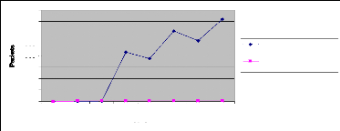
4000
3500
3000
2500
2000
1500
1000
500
0
1 2 3 4 5 6 7 8
Hours
Traditionnal Streaming Packets/Sec
Packets charging model Packets/sec
Figure 39: Comparative diagram between packet charging
model and traditional streaming. Source: Own drawing
As seen on the above result, there are a big difference
between traditional streaming and packets charging model. The range of packets
flow inside the network is extremely big for traditional streaming which can
make problem of relaying data from the server to the client, there can be
problem of packets loss during the traffic, but in case of packets charging
model, the range of packets flow inside the network is small as it is between 0
and 35 packets per second, that show the performance and quick relay of
multimedia services during the utilization of packets charging model.
(c) Packets loss
After comparing bandwidth during network traffic; as
realization all packets are not able to reach clients host i.e. that there are
packets lost along the way. The following table shows the number ofpackets lost
during live video streaming:
|
Hours
|
Packets/sec
|
|
18:06:49
|
4
|
|
18:06:50
|
2
|
|
18:06:51
|
12
|
|
18:06:52
|
2
|
|
18:06:53
|
10
|
|
18:06:55
|
7
|
|
18:06:56
|
12
|
Table 7: Packets loss inside the network
As tested inside a network which has a lot of application that
was running, some packets has been lost. As result, the minimum of packets lost
is 0 packets/sec and the maximum is 12 packets/sec.For examples at 18:06:54
there was not packets lost, the only reason was because there was not corrupted
packets.
As known, Packet loss can be caused by a number of factors,
including signal degradation over the network medium, oversaturated network
links, corrupted packets rejected in-transit or faulty networking hardware. In
our case, Packets loss has been caused by most ofthe above factors.
Lost or dropped packets can result in highly noticeable
performance issues or jitter with Streaming Technologies, Voice over IP, Online
Gaming and Videoconferencing, and will affect all other network applications to
a degree.
Some network transport protocols such as TCP provide for
reliable delivery of packets. In the event of packet loss, the receiver asks
for retransmission or the sender automatically resends any segments that have
not been acknowledged. Although TCP can recover from packet loss,
retransmitting missing packets causes the throughput ofthe connection to
decrease.
This drop in throughput is due to the sliding window protocols
used for acknowledgement of received packets. In some protocols, if a
transmitted packet is lost, it will be resent along with every packet that had
been sent after it. This retransmission causes the overall throughput of the
connection to drop.
Protocols such as UDP provide don't recovery for lost packets.
Applications that use UDP are designed to handle this type ofpacket
loss.25
25
http://en.wikipedia.org/wiki/Packet_loss,24
january,2007
(d) Hypothesis verification
To verify the hypothesis given in the first chapter, there has
been many tests made in order to show the performance and quick relay of
multimedia services inside the network; and tests showed that instead of
traditional streaming, it is possible to implement the IP packet charging
models for multimedia services which is a good choice because even the number
of packets lost is not big, and it can be helpful when trying to get a high
performance and quick relay of multimedia services.
CHAPTER V: CONCLUSION AND RECOMMENDATIONS
V.1 Conclusion
As principal objective ofthis project was:
> To analyze network performance when using traditional
streaming and packets charging models
> IP packet charging model implementation
> To analyze QoS variation during packets traffic i.e.
latency, jitter and bandwidth variation.
Most ofthose objectives have been achieved. To conclude this
project, there are many things that can be said such as:
> Network performance can be good when doing packets
charging model instead of doing the traditional streaming, because in Packet
charging model there is a technology called Packets scheduling which decrease
number of packets that are running inside the network.
> Latency is small when using packets charging model instead
of traditional streaming i.e. that there is a quick relay of multimedia
services.
V.2 recommendation
In this project, there are many recommendations, so that
recommendation will be addressed especially to all people who are interested in
multimedia and networking, and recommendations are following:
> To implement live video streaming by using different
operating system.
> To secure accessibility of live video streaming
> To implement a videoconferencing by using packets charging
model
> To implement E-learning by using live video streaming.
> To software engineers, they can conceive software that can
help to do live video streaming.
REFERENCES
> Books
1. Aura Ganz, Zvi Ganz, Kitti Wongthavarawat, Multimedia Wireless
Networks: Technologies, Standards, and QoS, Prentice Hall
> Electronic sources
1.
http://en.wikipedia.org/wiki/Comparative_research
2.
http://www.erg.abdn.ac.uk/users/gorry/course/intro-pages/lan.html
3.
http://www.erg.abdn.ac.uk/users/gorry/course/intro-pages/wan.html
4.
http://www.erg.abdn.ac.uk/users/gorry/course/intro-pages/ps.html
5.
http://www.webopedia.com/TERM/M/MAN.html
6.
http://www.raduniversity.com/networks/1994/osi/layers.htm
7.
http://www.webopedia.com/TERM/T/TCP.html
8.
http://www.cisco.com/univercd/cc/td/doc/cisintwk/ito_doc/ip.htm#wp4145
9.
http://en.wikipedia.org/wiki/Jitter_buffer#jitter_buffers
10.
http://www.webopedia.com/TERM/b/buffer.html
11.
http://serverwatch.webopedia.com/TERM/L/latency.html
12.
http://www.cisco.com/univercd/cc/td/doc/cisintwk/ito_doc/qos.htm
13.
www.webopedia.com/TERM/M/streaming.htm
14.
http://en.wikipedia.org/wiki/Unicast
15.
http://en.wikipedia.org/wiki/Packet_loss
16.
http://www.webopedia.com/TERM/r/router.html
17.
http://kbserver.netgear.com/kb_web_files/n101528.asp
| 

