IP Packet charging for multimedia services( Télécharger le fichier original )par SAIDI SAIBA et KAYISINGA Jean de DIEU National University of Rwanda - Bachelor's degree 2007 |

CHAPTER IV: ANALYSIS AND IMPLEMENTATION OF LIVE VIDEO STREAMING
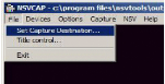
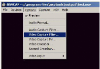
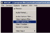
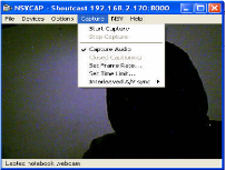
IV.3 live video streaming using nsv capture The first thing to do is to source (send) the video to a shoutcast compatible server to be streamed. To start the process of capturing video, the set capture destination must be selected IV.3.1 SET CAPTURE DESTINATION
Figure 24: NSV tools configuration to set capture destination Source: http://www.scvi.net/liveenc.htm, january 27,2007 The above Figure show where to click for getting the file configuration ofNSV capture. IV.3.2 SET CAPTURE DESTINATION FILE The configuration ofthe capture destination option
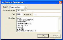
Figure 25: Set capture destination Source: http://www.scvi.net/liveenc.htm, january 27,2007 Output: Set to Shoutcast server
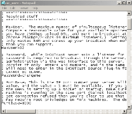
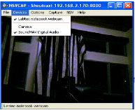
content-type: video/nsv - it can't be changed icy-metadata: 1 icy-name: WHITY TV - your station name icy-genre: video - type of genre icy-pub: 0E- publicly listed on Winamp TV directory icy-br: 128E- Estimated bitrate icy-url:http://1 92.168.2.170E- it can't be changed IV.3.3 NVS tools FOR DE VICES The following step is the selection of devices required for video and audio
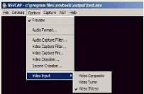
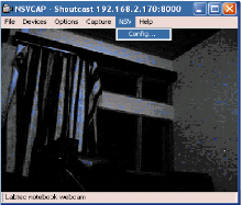
Figure 26: NVS tools for capturing cards Source: http://www.scvi.net/liveenc.htm, January 27, 2007 IV.3.4 SET CAPTURE DESTINATION Many capture cards have selections for composite, SVideo, or TV tuner, which must be configured according to the device connected. In this case the above options are disabled because ofusing a webcam.
Figure 27: Selection of video input Source: http://www.scvi.net/liveenc.htm, January 27,2007 The following step is the selection of Video standard and picture adjustment.
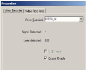
Figure 28: Video capture filter configuration Source: http://www.scvi.net/liveenc.htm, January 27,2007 IV.3.5 VIDEO DECODER CONFIGURATION In order to get video format that is compatible with the shoutcast, the Video standard must be as follows:
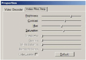
Figure 29: Video Decoder configuration Source: http://www.scvi.net/liveenc.htm, january27,2007 And any picture adjustment is done in this configuration window:
Figure 30: Video Proc Amp Source: http://www.scvi.net/liveenc.htmjanuary 27, 2007 IV.3.6 VIDEO CAPTURING PIN CONFIGURATION The following step is to set the device compress and set resolution to 320x240 for streaming, which is the preferred order of choice for the video codec. The following are some Video Format Preference:
Figure 31: Video Capture pin Source: Own result IV.3.7 VIDEO CAPTURING CONFIGURATION The other Video Format Preference that is listed may not work at all. This depends on whether or no the encoding tool can handle the conversion. The following option allows the capture of audio with the video and allows sound to be included in the video.
Figure 32: Video capture configuration Source: Own result To configure the encoder there are several steps such as:
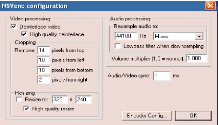
Figure 33: NSV configuration Source: Own result The `top' and `bottom' labels in this window are reversed.
Figure 34: NSV encoder configuration Source: Own result Video: Deinterlance with high quality for all «video outs» from other machines as NTSC is 512 lines interlaced. Webcam's direct screen captures are not interlaced. But some movies are interlaced and may need this enabled as well. Cropping: If the capture output does not fill the screen. There must be the configuration of pixels that must fit the screen. To run the server, the option captured helped to enable NSVcap to start capturing images.
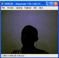
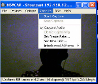
Figure 35: The first image to send to the client Source: Own result The following figure, show how to start capturing the image.
Figure 36: starting capturing the image Source: Own result The choice of Shoutcast as server is because it can stream faster, and it has been adapted to Real time streaming protocols. After all the above steps, the client will be able to watch in live the image captured. IV.4 Results analysis IV.4.1 LATENCY After carrying out the live video streaming, it is very important to test the latency time. The test during this research has been done in three different days in three different times, i.e. the morning, the day and the evening. Latency has been defined as the period of time that one component in a system is spinning its wheels waiting for another component; it is the reason why the table below showed how latency has been calculated during experiences by following images motions. The following table show the latency tested according to the motion of a gesture during the live video streaming seen on the streaming server and client 1.
Table 3: latency test Source: Own Result As shown in the above table, the latency in Packets charging model is not great that to show that there is a high performance and quick relay of live video. IV.4.2 BANDWIDTH In computer networks, bandwidth is often used as a synonym for data transfer rate the amount of data that can be carried from one point to another in a given time period. In this project, Number of packets per second helped to test network performance. Number of packets per second. Almost the same amount of processing needs to be done on a packet with 1500 byte payload as for a packet with a one byte payload. The number of packets per second determines the number of times the state table and, in case of no match there, filter rules have to be evaluated every second, determining the effective demand on the system. (a) Intrastation packets scheduling (When starting to send data local host) This case is Intrastation packet scheduling which follow the mechanism that retrieves a packet from a queue within the same host which has the following IP address 192.168.12.2
Table 4: Intrastation packets scheduling Source: Own Result Diagram
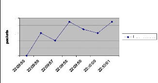
10 4 8 6 2 0 Intrastation packets scheduling Hours Packets/sec Figure 37: Intrastation packets scheduling Source: Own drawing The diagram shown above is explaining the behavior of packets during the intrastation packets scheduling inside the network, the number of packets inside the network increase in function of time, and it is varying between 0 and 10. As known, Intrastation packet scheduling is the packet scheduling mechanism that retrieves a packet from a queue within the same host; it is the reason why the packets traffic is varying between 0 and 10 packets per second. (b) The Interstation packet scheduling This case is the Interstation packet scheduling which follow the mechanism that retrieves a packet from a queue from different hosts.
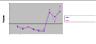
Table 5: Interstation packets scheduling: Source: Own result The above table can be shown in the following diagram which showed packets variation inside the network for two clients that are connected to the server. As said before, Interstation packet scheduling is packet scheduling mechanism that retrieves a packet from a queue from different hosts that can cause the augmentation of packets traffic inside the network. In this case packets traffic per second varies between 0 and 35. Diagram
25 20 30 15 10 5 0 1 2 3 4 5 6 7 8 9 10 Hours 192.168.10.2 Packets/Sec Figure 38: Interstation packets scheduling Source: Own drawing According to the above results, there can be a comparison with traditional streaming, as shown in the table 1, packets are Varying between 0 and 4000 packets per second, then by comparing those result with those of packets charging model the can be a big difference because the variation ofpackets during packet charging is very small and it is varying between 0 and 35. The following table shows the difference between traditional streaming and packets charging model; and it has been shown in the following comparative table between Traditional streaming and Packet charging model.
Table 6: Comparative table Source: Own result Diagram
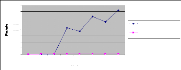
4000 3500 3000 2500 2000 1500 1000 500 0 1 2 3 4 5 6 7 8 Hours Traditionnal Streaming Packets/Sec Packets charging model Packets/sec Figure 39: Comparative diagram between packet charging model and traditional streaming. Source: Own drawing As seen on the above result, there are a big difference between traditional streaming and packets charging model. The range of packets flow inside the network is extremely big for traditional streaming which can make problem of relaying data from the server to the client, there can be problem of packets loss during the traffic, but in case of packets charging model, the range of packets flow inside the network is small as it is between 0 and 35 packets per second, that show the performance and quick relay of multimedia services during the utilization of packets charging model. (c) Packets loss After comparing bandwidth during network traffic; as realization all packets are not able to reach clients host i.e. that there are packets lost along the way. The following table shows the number ofpackets lost during live video streaming:
Table 7: Packets loss inside the network As tested inside a network which has a lot of application that was running, some packets has been lost. As result, the minimum of packets lost is 0 packets/sec and the maximum is 12 packets/sec.For examples at 18:06:54 there was not packets lost, the only reason was because there was not corrupted packets. As known, Packet loss can be caused by a number of factors, including signal degradation over the network medium, oversaturated network links, corrupted packets rejected in-transit or faulty networking hardware. In our case, Packets loss has been caused by most ofthe above factors. Lost or dropped packets can result in highly noticeable performance issues or jitter with Streaming Technologies, Voice over IP, Online Gaming and Videoconferencing, and will affect all other network applications to a degree. Some network transport protocols such as TCP provide for reliable delivery of packets. In the event of packet loss, the receiver asks for retransmission or the sender automatically resends any segments that have not been acknowledged. Although TCP can recover from packet loss, retransmitting missing packets causes the throughput ofthe connection to decrease. This drop in throughput is due to the sliding window protocols used for acknowledgement of received packets. In some protocols, if a transmitted packet is lost, it will be resent along with every packet that had been sent after it. This retransmission causes the overall throughput of the connection to drop. Protocols such as UDP provide don't recovery for lost packets. Applications that use UDP are designed to handle this type ofpacket loss.25 25 http://en.wikipedia.org/wiki/Packet_loss,24 january,2007 (d) Hypothesis verification To verify the hypothesis given in the first chapter, there has been many tests made in order to show the performance and quick relay of multimedia services inside the network; and tests showed that instead of traditional streaming, it is possible to implement the IP packet charging models for multimedia services which is a good choice because even the number of packets lost is not big, and it can be helpful when trying to get a high performance and quick relay of multimedia services. |
| |||||||||||||||||||||||||||||||||||||||||||||||||||||||||||||||||||||||||||||||||||||||||||||||||||||||||||||||||||||||||||||||||||||||