|

FACULTY OF ECONOMIC SCIENCE & MANAGEMENT
DEPARTMENT OF
INFORMATION SYSTEM &
MANAGEMENT
Academic year 2011-2012
A dissertation submitted in partial fulfillment of academic
requirement for the award of a Bachelors Degree in Information (Systems and)
Management
Under the guidance of
Pierre Celestin ZIRARUSHYA
REPUBLIC OF RWANDA
INDEPENDENT INSTITUTE OF LAY
ADVENTISTS
OF KIGALI (INILAK)
BP. 6392 Kigali, Rwanda
HOME RENTAL AND RELOCATION
SERVICES SYSTEM
submitted by
Alphonse MINANI Reg. No : 00606/2009
October 2012
DECLARATION
I, Alphonse MINANI hereby declare that the
project report entitled «HOME RENTAL AND RELOCATION SERVICES
SYSTEM» submitted in partial
Fulfillment of the requirement for the award of the degree of
Bachelors Degree in Information (Systems and)
Management is a record of bonafide project work carried out by myself
under the supervision of Pierre Celestin
ZIRARUSHYA. I further declare that the work
reported in this project has not been submitted, either in part or in full, for
the award of any other degree or diploma in this institute or any other
institute or university.
Kigali
Date: October 2012 Alphonse MINANI
INDEPENDENT INSTITUTE OF LAY ADVENTIST OF
KIGALI
(INILAK)
B.P. 6392 KIGALI, Tél:
55107311/55104697
E-mail:
contact@inilak.ac.rw
Website:
www.inilak.ac.rw
BONAFIDE CERTIFICATE
This is to certify that the project report entitled
«HOME RENTAL AND RELOCATION SERVICES SYSTEM
«submitted by Alphonse MINANI Reg.No00606/2009
to Independent Institute of Lay Adventists of Kigali in partial
fulfillment of the requirement for the award of the degree of Bachelors
degree in Information (Systems and) Management is a
record of bonafide work carried out by him under my supervision.
Pierre Celestin ZIRARUSHYA Pierre Celestin ZIRARUSHYA
SUPERVISOR HEAD OF DEPARTMENT
October 2012 October 2012
Accredited by the Ministerial Order No 002/09 0f 09/04/2009
granting the Definitive Operating License
DEDICATION

The Almighty God
II
ACKNOWLEDGEMENT
The satisfaction that accompanies the successful completion of
any task would be incomplete without the mention of people whose ceaseless
cooperation made it possible, whose constant guidance and encouragement crown
all efforts with success.
We are grateful to our project supervisor Mr. Pierre
Celestin ZIRARUSHYA for the guidance, inspiration and constructive
suggestions that helped us in the preparation of this project.
We make a mention in special recognition of our parents,
brothers, sisters and all relatives for the material, moral and
financial support.
We appreciate friends for untiring encouragement.
We are deeply indebted to the help got from Emmanuel MUHIRWA
and François GASHABIZI'S Family
We are beholden to all our classmates for their positive
contribution to the accomplishment of this work.
May God still keeping you all in his safe hands and help you
in the continuous and better accomplishment of your daily tasks.
Kigali
October 2012 Alphonse MINANI
iii
TABLE OF CONTENTS
DEDICATION i
ACKNOWLEDGEMENT ii
TABLE OF CONTENTS iii
LIST OF TABLES vi
LIST OF FIGURES vii
ACRONYMS ABBREVIATIONS AND NOMENCLATURE viii
ABSTRACT x
CHAPITER ONE: GENERAL INTRODUCTION 1
1.1 INTRODUCTION 1
1.2 BACKGROUND 2
1.3 PROBLEM STATEMENT 2
1.4. MOTIVATION 2
1.5 OBJECTIVES 3
1.5.1 General Objectives 3
1.5.2 Specific Objectives 3
1.6 CHALLENGES 3
1.7 ESSENCE OF OUR PROJECT 4
1.8 SCOPE OF OUR STUDY 4
1.9 STATEMENT OF ASSUMPTION 4
1.10 EXPECTED RESULTS 4
CHAPTER TWO: LITERATURE REVIEW 7
2.1 GENERAL INTRODUCTION 7
2.2 SPECIFIC TERMINOLOGY 7
2.2.1 System Analysis and design 7
2.2.2 Computer Software 8
2.2.3 Database concepts 9
2.2.4 Data Modelling 10
2.2.6 Data warehouse 12
2.2.7 Client/Server architecture 13
iv
2.2.8 Tools, techniques and languages used developing software
14
2.3 COMPARATIVE STUDY 16
2.3.1 Online Application for Residential Information System 16
2.3.2 Management System of Rooms And Restaurant. 16
2.4 PERSONAL CONTRIBUTION 16
CHAPTER THREE: ANALYSIS OF THE EXISTING SYSTEM 17
3.1 INTRODUCTION 17
3.2 BACKGROUND OF INTERNATIONAL ORGANIZATIONS STUDIED 17
3.3 VISIONS AND MISSIONS 18
3.4 LIMITATION OF CURRENT SYSTEM 19
3.5 EXISTING SYSTEM 19
CHAPTER FOUR: ANALYSIS AND DESIGN OF THE PROPOSED SYSTEM 21
4.1 INTRODUCTION 21
4.2 SOFTWARE DEVELOPMENT MODEL 21
4.2.1 Software Development Life Cycle Model 21
4.3 STUDY OF NEW SYSTEM 22
4.4 STRUCTURAL DIAGRAM 23
4.4.1 Function Diagrm 23
4.4.2 Data Flow Diagram 24
4.4.4 Context diagram 24
4.5 WAYS OF RECORDING INFORMATION 28
4.5.1 Entity Relationship Diagram 28
4.5.2 Designing the ERD 28
4.5.3 Entity Relationship Diagram 29
4.6 CONCEPTUAL MODEL OF DATA 30
4.7 LOGICAL DATA MODEL 31
4.8 THE CONCEPTUAL LEVEL 31
4.8.1 The Treatment Conceptual Model 31
4.8.2 Treatment Conceptual Model for House information 33
4.8.3 Treatment Conceptual Model for confirming registration
33
4.8.4 Treatment Conceptual Model for services information 34
4.9 DATA DICTIONARY 34
V
4.10 ORGANIZATIONAL MODEL OF PROCESS 36
4.11 PHYSICAL DATA MODEL 38
4.12 ADVANTAGE OF THE NEW SYSTEM 39
CHAPTER FIVE: IMPLEMENTATION OF THE NEW SYSTEM 40
5.1INTRODUCTION 40
5.2 System Design 40
5.3 The system implementation 44
5 .4 Verification of Hypothesis 44
CHAPTER SIX: FUTURE ENHANCEMENT 45
6.1 CONCLUSION 45
6.2 RECOMMENDATION 45
REFERENCES 46
BOOKS AND PUBLICATIONS 46
DOCUMENT AND REPORT 46
ELECTRONIC REFERENCES 46
APPENDIES 47
APPENDIX 1: OARIS-DFD level zero A
APPENDIX 2: ERD-Management System of Rooms and Restaurant B
vi
LIST OF TABLES
Table 1: Cardinalities 30
Table 2: HRRSS Data dictionary 36
Table 3: Organizational Model of Process 38
vii
LIST OF FIGURES
Figure 1: Role of data warehouse 13
Figure 2: Client /Server architecture 14
Figure 3: software development life cycle 22
Figure 4: HRRSS Function diagram 23
Figure 5: HRRSS Context diagram 25
Figure 6: DFD level 0 for whole HRRSS 26
Figure 7: DFD Level 1 for User Management of HRRSS 26
Figure 8: DFD Level 1 for User Management 26
Figure 9:DFD Level 1 for Service Management 27
Figure 10: DFD Level 1 for House Management of HRRSS 27
Figure 11:DFD Level 1 for House Management 27
Figure 12: Entity Relationship Diagram for HRRSS 29
Figure 13: Treatment Conceptual Model for House information
33
Figure 14: Treatment Conceptual Model for confirming
registration 33
Figure 15: Treatment Conceptual Model for services information
34
Figure 16: Physical Data Model 39
Figure 17: HRRSS database 40
Figure 18: HRRSS login form with data 41
Figure 19: Rcord of services(Club of language teach) 41
Figure 20: HRRSS House information record 42
Figure 21: Form for checking details of any service 42
Figure 22: Report of house and services on a location 43
Figure 23: Report of Expatriate, house and owner on a location
43
Figure 24: OARIS-DFD level zero A
Figure 25: ERD-Management System of Rooms and Restaurant B
VIII
ACRONYMS ABBREVIATIONS AND NOMENCLATURE
4NF : Fourth Normalization form
ASP : Active Server Page
CGI : Common Gateway Interface
CMD : Conceptual Model of Data
CSS : Cascading Style Sheet
DB : Data Base
DBMS : Data Base Management System
DFD : Data Flow Diagram
E-R : Entity Relationship
ERD : Entity Relationship Diagram
ERDM : Entity Relationship Data Model
FTP : File transfer Protocol
HRRSS : Home Rental and Relocation Services
System
HTML : Hypper Text make-up Language
HTTP : Hypper Text Transfer Protocol
IMAP : Internet Message Access Protocol
INILAK : Independent Institute of Lay
Adventist Of Kigali
ISM : Information System Management
LAN : Local Area Network
NNTP : Network News Transfer Protocol
NOS : Network Operating System
NUR : National University of Rwanda
OMP : Organizational Model of Process
PC : Personal Computer
PDM : Physical Data Model
PHP : Personal Home Page or Hypertext
Preprocessor
POP3 : Post Office Protocol
SNMP : Simple Network Management Protocol
SQL : Structured Query Language
ix
SSL : Secure Sockets Layer
URL : Universel Resource Locator
VBScript : Visual Basic Script
WWW : World Wide Web
XAMPP : X Apache, MySQL Perl and PHP
X
ABSTRACT
In Rwanda there are not any company that can facilitate new
coming people to locate homes and other basic services. When an expatriate
arrive in Rwanda is obliged to leave in a hotel while looking for a home. This
expatriate take long time for getting the needed home and relocation services.
That's why the introduction of new system for home rental and relocation
services is most important and necessary. The analysis of old system, making an
interview to people who work in international organization can be a help for
design the system. This system will allow locating and rent house anywhere the
user will be. The user will also locate services.
1
CHAPITER ONE: GENERAL INTRODUCTION
1.1 INTRODUCTION
Kigali as other cities in the world is being extended and many
houses are constructed. People visit and get are deployed in and also need to
rent houses or to get some services. It is still difficult to find a good house
in short time and know exactly where to find these or those services.
The main object of this project is to develop and implement a
web based application called «a home rental and relocation services system
» in order to implement a web based property management system to help
International organizations to provide reliable services to its expatriate
employees.
The methodology used was «software development life cycle
model» because it is very simple to understand and use. In a software
development life cycle model, each phase must be completed in its entirety
before the next phase can begin. At the end of each phase, a review takes place
to determine if the project is on the right path and whether or not to continue
or discard the project.
The first activity in development phase was to study the
existing system; this helped in understanding the real needs of expatriate.
The second activity carried out was actually the design of
system; the goal of this phase was to produce a model or representation that
was going to be used to build the new system.
The third activity in the development part was the coding
phase. The aim of this phase was to translate the design into the code in php,
xml and action script programming language.
The final activity was to test the system in order to find out
if it meets all specified requirements.
After this, we verified and confirmed the hypothesis that our
application can be used improved to provide quick and best services.
2
Recommendations have also been suggested for further research
to enhance, revise and add more functionality to the prototype developed
here.
1.2 BACKGROUND
Rwanda is an independent country where many countries have
representatives for diplomatic and
cooperation missions (Embassies). There are also international
organizations in which Rwanda is a member like United Nations. In all those
missions and organizations there work Rwandan and non-Rwandan citizens. For
non-Rwandan citizens who work for those organizations and missions live in the
country for long period that goes up one year. Coming to Rwanda those employees
as they have to stay a long time they may or not wish to be accompanied by
their partners and their children.
1.3 PROBLEM STATEMENT
The deployed expatriate may need to be moved with his family.
Refer to the period of mission
given, these will arise also the need of some services to them
and or their family. Here we can say accommodation (home or house to live in),
Education (school for children), teacher for the family (language teaching),
job for partner (wife or husband), markets, hospitals, ....
Actually when a deployment is done, an employee moves without
being informed about services available at the place where he/she is deployed.
This employee will get information about those services, when she/he reach the
place and it is up to the expatriate to look for those services accompanied by
one of the organization or mission. While waiting the end of these
operations
the expatriate live in a hotel.
The fact of looking for accommodations (houses or homes to live
in) non-Rwandan citizen even
Rwandan citizen have to find a local person who may know
exactly where to find an accommodation. Together they take time to visit that
house or home.
1.4. MOTIVATION
This project is more important for us while it will help us to
apply courses learnt in class.
The international organizations and diplomatic missions will
get facilities of getting a well done system for improvement of its services
about home rental and relocation services this system will
3
provide online services updation and facility request.
Everything is posted electronically so information can be got easily without
moving here and there looking for any services.
1.5 OBJECTIVES
1.5.1 General Objectives
The introduction of this system will help so far not only the
management of the new employee in any organization or mission but also this
employee will be facilitated to get necessary information about accommodation,
education, job for partner and language teaching. The owners of houses for rent
will have an easy way of advertising their houses. Companies and organizations
that look for employees will have a way of posting qualification and
requirement for applications.
1.5.2 Specific Objectives
After realizing services needed by deployed employees, and
owners of houses In Rwanda particularly at Kigali, the specific objectives of
our system will be: Posting home or house for rent with its required details,
to different users of our system, posting school with its detailed information,
posting links of job vacancies, and all requirements to users of the system.
1.6 CHALLENGES
This system of home rental and relocation services would be or
bring the solution to problem that non-Rwandan citizen meet but information or
details needed about home and schools could not well provided on the system.
This is the big and most challenge our system could have,
because of the lake of information about homes for rent and school would make
our system meaningless while these homes and schools are basic elements in our
system.
4
1.7 ESSENCE OF OUR PROJECT
There will be a way of marking an occupied home to allow
client to know the status of homes posted. People will be encouraged to post
required information about their schools and being shown how it is their
interest to post their schools information. People will be encouraged to post
all information accurately.
1.8 SCOPE OF OUR STUDY
This system would be used by Rwanda Development Board and or
Rwanda Housing Authority in its activities for country's development. The use
of this system will be open to all people from international organizations and
diplomatic missions and even else one wish services provided by this system.
1.9 STATEMENT OF ASSUMPTION
Those house or home should have normal standing in terms of being
a residential area.
Those house or home to be posted should be accessible in terms
of evacuation when any safety problem occurs.
Schools to be posted on home rental and relocation services
system should be accredited by the government and being able to provide or
deliver lessons on in both languages English and French. These schools should
have a good reputation.
Each and every user of home rental and relocation services
system should be registered and login the system. The registration is done
once.
1.10 EXPECTED RESULTS
With our project and system that will be built about,
everything will be Clear and available to those who have the access on the
system. It will be up to the employee to decide whether he/she is happy to live
in hotel, or not. It will be up to him/her to mark the quality of services
(necessary document, accommodation, Education, teacher for the family, job for
partner) needed even being at his /her home countries without moving .
5
The owner of homes or houses for rent will have the access of
posting their full addresses on which they will be informed when their houses
will be chosen; location, photos, and price of their houses in order to permit
the client to know well the quality.
The quality of services provided by organizations located in
Rwanda will be increased and production may also be increased.
Information will be posted properly in the system which will
help in the retrieval of information. All operations would be done correctly
and it ensures that whatever information is coming from the center is accurate.
Any type of information would be available whenever the user requires.
The system will be easy to operate and it will be such that it
can be developed within a short period of time and fit in the limited budget of
the user.
1.11 ORGANIZATION OF THE REPORT
This project of home rental and relocation services system is
composed with six chapters with what:
The first chapter, «General introduction» introduces
the project and the background of the county which one play the major role in
our project while it is studied case. Generally and specifically with this
chapter we will introduce the objectives of our project. The difficulty and
methods in problem solving will be found out. We will show condition in which
the solution we are proposing could be applicable. As every work done our
project is delimited in this chapter.
The second chapter, «Literature Review» will state
specification terminology, comparative studies of works done on home rental and
relocation services. Here the difference of our project with other similar
works or projects done will be shown.
The third chapter, «Analysis of Existing System»
shows all analysis we have made on home rental and relocation services at, and
how that system would work currently. We will also analyze all features and
characteristics that will be adopted by our system.
6
The fourth chapter, «Analysis and Design of the Proposed
System» will describe the engineering specifications and target critically
evaluating the existing benchmarks and specifically identifying the gaps which
our project is intended to fill. We will show how concepts evolved and what
will be the requirement specifications, the block diagram, the system
architecture indicating various modules and entity relation diagram, data flow
diagram, data dictionary .
The fifth chapter, «Implementation of System» will
reflect the development of our project, technology tools we have chosen to use,
important modules' interfaces that our system will show, and finally testing
result and discussions.
At the end of our work there will be the last chapter,
«Future Enhancement» which will summarize key aspects of our project
and state conclusion that we have been able to draw. We will outline our future
work and identify the benefits from our project.
7
CHAPTER TWO: LITERATURE REVIEW
2.1 GENERAL INTRODUCTION
In this chapter three main part are developed and discussed on
the Specific terminology, the Comparative study of home rental and relocation
services and our personal contribution.
The purpose of the first part is to provide a brief
description about terms that are used during development of this project. It
deals with theoretical concepts and fundamentals that support this project. It
provides definitions and characteristics of technologies used.
The second part of this chapter will be focused on the
comparative study of our work done in attempt to solve the home rental and
relocation services problems.
The last session of this chapter is my contribution to solve
home rental and relocation services problems but through the different ways
from consulted works.
2.2 SPECIFIC TERMINOLOGY
Before developing the information system, basic concepts must
be illustrated for developer or user. Definitions and characteristics of
technologies used are described below.
2.2.1 System Analysis and design 2.2.1.1 System
A System is a group of elements, components, or devices that
are assembled to serve a common purpose. In a technological system, this refers
to all hardware, software, networks, cables, peripheral equipment, information,
data, personnel, and procedures (i.e. all technology resources) that comprise a
computer environment.
2.2.1.2 Information System
A set of people, procedures and resources that collects,
transforms and disseminates information in an organization; a system that
accepts data resources as input and processes them into information products as
output; a system that uses the resources of hardware, software and
8
people to perform input, processing, output, storage and
control activities that transform data resources into information products; a
purposefully designed system that brings data, computers, procedures, and
people, etc. It means an interconnected set of information resources under the
same direct management control that shares common functionality. A system
normally includes hardware, software, information, data, applications,
communications, and people.
It is also an organized collection, storage, and presentation
system of data and other knowledge for decision making, progress reporting, and
for planning and evaluation of programs. It can be either manual or
computerized, or a combination of both. The organized collection, processing,
transmission, and dissemination of information in accordance with defined
procedures, whether automated or manual. Information systems include
non-financial, financial, and mixed systems.
2.2.1.3 Automated information system
An assembly of computer hardware, firmware, and/or software
configured to collect, create, communicate, compute, disseminate, process,
store, and/or control data or information. In telecommunications, the term
automated information system is an assembly of computer hardware, software,
firmware, or any combination of these, configured to accomplish specific
information-handling operations, such as communication, computation,
dissemination, processing, and storage of information. Included are computers,
word processing systems, networks, or other electronic information handling
systems, and associated equipment.
2.2.2 Computer Software
Software is a generic term for organized collections of
computer data and instructions, often broken into two major categories: System
software that provides the basic non-task-specific functions of the computer,
and Application software which is used by users to accomplish specific
tasks.
System software is responsible for controlling, integrating,
and managing the individual hardware components of a computer system so that
other software and the users of the system see it as a functional unit without
having to be concerned with the low-level details such as transferring data
from memory to disk, or rendering text onto a display. Generally, system
software consists of an operating system and some fundamental utilities such as
disk formatters,
9
file managers, display managers, text editors, user
authentication (login) and management tools, and networking and device control
software.
Application software, on the other hand, is used to accomplish
specific tasks other than just running the computer system. Application
software may consist of a single program, such as an image viewer; a small
collection of programs (often called a software package) that work closely
together to accomplish a task, such as a spreadsheet or text processing system;
a larger collection (often called a software suite) of related but independent
programs and packages that have a common user interface or shared data format,
such as Microsoft Office, which consists of closely integrated word processor,
spreadsheet, database, etc.; or a system software, such as a database
management system, which is a collection of fundamental programs that may
provide some service to a variety of other independent applications.
Software is created with programming languages and related
utilities, which may come in several of the above forms: single programs like
script interpreters, packages containing a compiler, linker, and other tools;
and large suites (often called Integrated Development Environments) that
include editors, debuggers, and other tools for multiple languages.
2.2.3 Database concepts 2.2.3.1. Data
The term data refers to a fact, text, graphics, images, and
videos segments that they have the same meaning in the users' environment. That
could be recorded and stored on computer media. Data are distinct pieces of
information, usually formatted in a special way.
2.2.3.2 Database
The term database means a collection of related data
organized in a way that can be processed by application programs. By organized
we mean that the data are structured so as to be easily restored, manipulated
and retrieved by users. By related we mean that the data describe a domain of
interest to a group of users and that the users can use the data to answer
questions concerning that domain. Database may be of any size and complexity. A
database management system
10
(DBMS) consists of a set of licensed programs that define and
maintain the structure of the database and provide support for certain types of
application programs.
2.2.3.3 Database system
Database system is basically a computerized record-keeping; it
is a computerized system whose overall purpose is to store information and to
allow users to retrieve and update that information on demand.
The information in question can be anything that is of
significance to the individual or organization concerned-anything, in other
words, that may be necessary to the decision-making processes involved in the
management of that organization.
2.2.3.4 Database management system
Database management system is the software that handles all
access to the database. A major role of database management system is to allow
the user to deal with the data in abstract terms, rather than as the computer
stores the data.
Database management system is computer program (or more
typically, a suite of them) designed to manage a database (a large set of
structured data), and run operations on the data requested by numerous clients.
Typical examples of DBMS use include accounting, human resources, and customer
support systems. Originally found only in large organizations with the computer
hardware needed to support large data sets, DBMSs have more recently emerged as
a fairly standard part of any company back office.
DBMS's are found at the heart of most database applications.
Sometimes DBMSs are built around a private multitasking kernel with built-in
networking support although nowadays these functions are left to the operating
system.
2.2.4 Data Modelling
Data model is the analysis of data object and their
relationship to other data objects. Is often the first step in database design
as the designers first create a conceptual model of how data items relate to
each other.
11
2.2.4.1 Entities
Things or objects of significance to the business, whether
real or imagined about which the business must collect and maintain data, or
about which information needs to be known or held.
2.2.4.2 Attributes
There are properties or characteristics of an entity type that
is of interest to the organization or the entity's characteristics.
2.2.4.3 Identifiers
Attributes that name, or identify entity instances. For
example Employee instances could be identified by Social Security Number,
Employee Number.
2.2.4.4 Relationships
Relationships are the glue that holds together the various
components of an E-R model. Intuitively, a relationship is an association among
the instances of one or more entity types that is of interest to the
organization.
2.2.4.5 Entity-Relationship Diagram
It is a pictorial representation of the entities and the
relationships between them. It allows the participants in the meeting to easily
see the information structure of the application.
2.2.4.6 Normalization
Normalization is the process of organizing data to minimize
redundancy. Normalization usually involves dividing a database into two or more
tables and defining relationships between the tables. The objective is to
isolate data so that additions, deletions, and modifications of a field can be
made in just one table and then propagated through the rest of the database via
the defined relationships.
12
2.2.6 Data warehouse 2.2.6.1 Definition
A subject-oriented, integrated, time-variant, no updatable
collection of data used in support of management decision making processes and
business intelligence.
Formal systems definition of a data warehouse is a computer
database and its supporting components that is:
Subject oriented, meaning that the data in the database is
organized so that all the data elements relating to the same real-world event
or object are linked together;
Integrated, meaning that the database contains data from most
or all of an organization's operational applications, and that this data is
made consistent.
Time variant, meaning that the changes to the data in the
database are tracked and recorded so that reports can be produced showing
changes over time;
No updatable, meaning that data in the database is never
over-written or deleted, but retained for future reporting and users access the
data warehouse by means of variety of query languages and analytical tools.
Results may be fed back to data warehouse and operational databases.
A data warehouse is a store of enterprise data that is
designed to facilitate management decision making. A data warehouse includes
not only data but also tools, procedures training personnel, and other
resources that make access to the data easier and more relevant to decision
makers. The goal of the data warehouse is to increase the value of
organization's data asset.
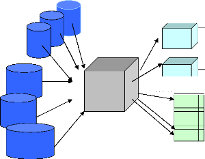
The following is the figure explaining the role of data
warehouse which is to store extracts from operational data and make those
extracts available to users in a useful format.
Images
Other data
Files
DB
DB
DB
Data
warehouse
Departmental server
Departmental
User computer
User computer

13
Figure 1: Role of data warehouse
Source: DAVID M.KROENKE, processing
fundamental design and Implementation, Sixth edition, p.382.
The data can be extracts from databases and files, but it can
also be document images, recordings, photos, and other no scalar data. The
source data could also purchased from other organizations. The data warehouse
stores the extracted data and also combines it, aggregates it, transforms it,
and makes it available to users via tools that are designed for analysis and
decision making
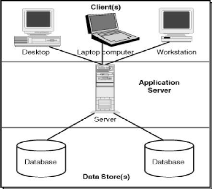
2.2.7 Client/Server architecture
A network architecture in which each computer or process on
the network is either a Client or a Server. Servers are
powerful computers or processes dedicated to managing disk drives (file
servers), printers (print servers), or network traffic
(network servers ). Clients are PCs or workstations on which users run
applications. Clients rely on servers for resources, such as files, devices,
and even processing power.
14
Figure 2: Client /Server architecture Source:
www.webbasedprogramming.com
2.2.8 Tools, techniques and languages used developing
software 2.2.8.1 JavaScript
A scripting language developed by Netscape to enable Web
authors to design interactive sites. Although it shares many of the features
and structures of the full Java language, it was developed independently.
JavaScript can interact with HTML source code, enabling Web authors to spice up
their sites with dynamic content. JavaScript is endorsed by a number of
software companies and is an open language that anyone can use without
purchasing a license. It is supported by recent browsers from Netscape and
Microsoft, though Internet Explorer supports only a subset, which Microsoft
calls Jscript
2.2.8.2 Apache
Apache is generally recognized as the world's most popular Web
server (HTTP server). Originally designed for UNIX servers, Apache has been
ported to Windows and other Network Operating Systems (NOS). The name "Apache"
derives from the word "patchy" that the Apache developers used to describe
early versions of their software.
Apache provides a full range of Web server features, including
CGI, SSL, and virtual domains. Apache also supports plug-in modules for
extensibility. Apache is reliable, free, and relatively easy to configure.
15
The Apache HTTP server is free software distributed by the
Apache Software Foundation. The Apache Software Foundation promotes various
free and open source advanced Web technologies.
2.2.8.3 PHP
PHP is an open source server side programming language
extensively used for web scripts and to process data passed via the Common
Gateway Interface from HTML forms etc. PHP can be written as scripts that
reside on the server and may produce HTML output that downloads to the web
browser. Alternatively, PHP can be embedded within HTML pages that are then
saved with a .php file extension.
In an HTML document, PHP script (similar syntax to that of
Perl or C) is enclosed within special PHP tags. Because PHP is embedded within
tags, the author can jump between HTML and PHP (similar to ASP and Cold Fusion)
instead of having to rely on heavy amounts of code to output HTML. And, because
PHP is executed on the Server, the client cannot view the PHP code.
PHP can perform any task that any CGI program can do, but its
strength lies in its compatibility with many types of database. Also, PHP can
talk across networks using IMAP, SNMP, NNTP, POP3, or HTTP.
2.2.8.4 HTML
Hyper Text Markup Language, the coding language used to create
hypertext documents for the World Wide Web. In HTML, a block of text can be
surrounded with tags that indicate how it should appear (for example, in bold
face or italics). Also, in HTML a word, a block of text, or an image can be
linked to another file on the Web. HTML files are viewed with a World Wide Web
browser.
2.2.8.5 Edit Plus
Edit plus is an Internet-ready 32-bit text, HTML, and code
editor for Windows. It offers many features for Web page authors and
programmers, including syntax highlighting for HTML, CSS, PHP, ASP, Perl,
C/C++, Java, JavaScript, and VBScript. It is possible to use a seamless Web
browser for previewing HTML pages, and FTP commands for uploading local files
to an FTP
16
Server. Other features include HTML toolbar, user tools, line
number, ruler, URL highlighting, auto-completion, clip text, column selection,
powerful search and replace, and multiple undo/redo.
2.3 COMPARATIVE STUDY
In this section, we are going to describe some works which
have similarity with this work. Those we have referred to are; Online
application for residential information system, Management system of rooms and
restaurant, submitted in partial fulfillment of academic requirement for the
award of a Bachelors Degree in Information (Systems and) Management for the
year 2011 at NUR and INILAK .
2.3.1 Online Application for Residential Information
System
This one have made by NTAWUMENYIKIZABA Abdullah
who worked about residential information to rent and or to sell for people in
Kigali. The similarity between these systems with this system is on the way of
renting a house using an online system, but quit different, while this system
will post houses based on international standard requirement that focus on are
and safety.
2.3.2 Management System of Rooms And Restaurant.
This one have made by KWIZERA Hilaire who worked about on how
a student at KIST may get a room easily. The similarity between these systems
with our system is on the way of finding where to live for a certain period of
time to a person using an online or automated system.
2.4 PERSONAL CONTRIBUTION
Our contribution is to provide useful data base which contain
information about home, renting home, and relocation of services. Expatriate
will enjoy quick and good services.
17
CHAPTER THREE: ANALYSIS OF THE EXISTING
SYSTEM
3.1 INTRODUCTION
This chapter describe the analysis on how new employee for
expatriates gets home for rent and relocation services when they are deployed
in one of international organizations or missions represented in Rwanda. It
also illustrates the problems found on the ways operations on home for rent is
found and how relocation services are delved in those organizations or
missions.
3.2 BACKGROUND OF INTERNATIONAL ORGANIZATIONS STUDIED
Rwanda is a landlocked country situated in central Africa, bordered to the
north by Uganda, to the east by Tanzania, to the south by Burundi, to the west
by the Democratic Republic of Congo. Rwanda is famously known as the scene of
the 1994 genocide committed on Tutsis. Rwanda has tremendous progress in many
areas of social welfare, with the help of the international organizations and
friend countries through diplomatic missions. These international organizations
and diplomatic missions in their activities send experts in different domain
for different mission and purposes.
We have taken some of those international organizations and
diplomatic missions as case of study looking for information and see how new
employees get home rental and how relocation services that related to our
research are operated:
· European Union is an organization for cooperation
between governments. It was born in the 1950s with the aim of bringing together
the nations and people of Europe in the aftermath of World War II. In 50 years,
the European Union has brought together 27 countries, totaling population of
almost 500 million in the year 2008.
In Rwanda European Union and European Union member states, is
the major contributor of the aid provided to Rwanda. Its office is located at
Kacyiru 1807, Boulevard de l'Umuganda in Aurore house opposite Umubano hotel.
Five of 27 Members states are represented in Rwanda: Belgium, Germany, the
Netherlands, the United Kingdom, and the Swedish cooperation.
·
18
International Criminal Tribunal for Rwanda was established for
the prosecution of persons responsible for genocide and other serious
violations of international humanitarian low committed in the territory of
Rwanda between 1 January 1994 and 31 December 1994.
The seat of the Tribunal is located in Arusha, United
Republic of Tanzania in Arusha International Conference Centre, but the Office
of the Prosecutor is located at Kigali in Amahoro Hotel behind Amahoro National
Stadium.
· United Nations Development Program is the United
Nations' global development network, advocating for change and connecting
countries to knowledge, experience and resources to help people build a better
life.
In Rwanda the United Nations Development
Program offices are located in Kigali City at Avenue de l'Armee 12
3.3 VISIONS AND MISSIONS
European Union: The primary objectives of
European Union development cooperation is the eradication of poverty in the
context of sustainable development, including the pursuit of the millennium
development goals. The European Union aid aims to improve basic physical and
social infrastructures and productive potential as well as to strengthen
democratic state institutions. This support can also help poor countries
benefit from international trade opportunities and attract more inward
investment to broaden their economic base.
International Criminal Tribunal for Rwanda:
When International Criminal Tribunal for Rwanda was created the
purpose was to contribute to the process of national reconciliation in Rwanda
and to the maintenance of peace in the region. It may also deal with the
prosecution of Rwandan citizens responsible for genocide and other such
violations of international law committed in the territory of neighboring
States during the same period.
United Nations Development Program: United
Nations Development Program is a solution-oriented, knowledge-based development
organization, including the millennium development
19
goals. The millennium development goals provide a framework
for the entire United Nations system to work coherently together toward a
common end. United Nations Development Program, global development network on
the ground in 177 countries and territories, is in a unique position to
advocate for change goals, connect countries to knowledge and resources, and
coordinate broader efforts at the country level.
3.4 LIMITATION OF CURRENT SYSTEM
· It is difficult to access to the necessary information
· The information is not update
· It is hard to know where to find services or home for
rent
· It takes lot of time to find services
· The person in charge of home rental is not organized
while new employee is coming.
3.5 EXISTING SYSTEM
The process of moving to Rwanda for expatriates can be very
complicate. To relocate to Rwanda it is best to consult a local person
(Rwandan) who has comprehension and knowledge in what it entails.
In reality it is so difficult to know where to locate
relocation services and homes or houses for rent and how to find them.
In each one of the international organizations or missions
there is a person in charge of home rental or house for rent to new coming
employees. Even if this person is in charge of houses for rent he or she has
also other tasks for his or her daily activities.
While looking for a home rental or house for rent he or she
collaborates with different local person who often do the business of finding
house for rent and or for sell. These people called «Commissionaire»
don't care about the area, position, format that house or home possess or
20
standard rules of residenting. Their target is to find a home
or house based on the price and rooms that a client specified.
Generally this person in charge of home rental looks for a
home or house after being informed that there is an expatriate who is going to
come to the organization or mission. At the arrival of the new employee who is
an expatriate is informed by the person in charge of home rental about the
house found for him or her. The expatriate as newcomers in the country and
specifically in organization or mission most time confirms that house or home
found but he or she cannot confirm and request the person in charge to look for
another one depending on criteria given.
About the relocation services : education; teacher for
families; job for partners and other services related or not related that the
expatriate will need, are looked for by the expatriate on his or her
arrangement.
This system presents some weaknesses referring to how it is
done currently. That is why making it automated and accessed to everyone
concerned, may improve its performance and management.
21
CHAPTER FOUR: ANALYSIS AND DESIGN OF THE
PROPOSED
SYSTEM
4.1 INTRODUCTION
This chapter describes how about the system could be best
referring to the existing one in order to help users (Expatriate, managers from
international organizations that are represented in Rwanda, house holders,
school holders, and language teaching professionals)to access and post
information about home rental and relocation services as it have been
introduced in chapter one of this project.
4.2 SOFTWARE DEVELOPMENT MODEL
The expected outcome to this system would be achieved if the
software development life cycle model is used as the development of software
product.
4.2.1 Software Development Life Cycle Model
As with most undertakings, planning is an important
factor in determining the success or failure of any software project.
Essentially, good project planning will eliminate many of the mistakes that
would otherwise be made, and reduce the overall time required to complete the
project. As a rule of thumb, the more complex the problem is, and the more
thorough the planning process must be. Most professional software developers
plan a software project using a series of steps generally referred to as the
software development life cycle. A number of models exist that differ
in the number of stages defined, and in the specific activities that take place
within each stage.
Software development life cycle model is a framework that
describes the activities performed at each stage of a software development
project.
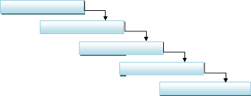
Software development life cycle model refer to
linear-sequential life cycle model is the most common and classical of life
cycle models. It is also called waterfall model that could be explained in five
steps below.
REQUIREMENT
DESIGN
IMPLEMENTATION
TESTING
MAINTENANCE
22
Figure 3: software development life cycle
· Requirements define needed information, function,
behavior, performance and interfaces.
· Design is based on data structures, software
architecture, interface representations, algorithmic details.
· Implementation focus on source code, database, user
documentation.
· Testing is an investigation conducted to provide
stakeholders with information about the quality of the product or service under
test. Test techniques include, but are not limited to, the process of executing
a program or application with the intent of finding software bugs (errors or
other defects).
· Maintenance is the modification of a software product
after delivery to correct faults, to improve performance or other
attributes.
4.3 STUDY OF NEW SYSTEM
The system that we are trying to develop is based on a process
of continuous quality improvement which links the quality areas of houses for
rent that will be provided by the owners, the quality of education from schools
as they will be proven by owners.
This system will help users settle into their new homes and
lifestyle by spending time taking them around, or simply acting as resource
from general information, such as who to call in case of languages teaching and
school for children, such a where to browse in case of job looking for.
4.4 STRUCTURAL DIAGRAM
The exact meaning of home rental and relocation services
system is explained in the following diagram.
4.4.1 Function Diagrm
Function diagram is used to show system's functions that will be
constructed. In addition,
function diagram will also be used to determine the appearance
of smaller process in that flow chart. In functional diagram, a function is
divided into many smaller functions and each smaller function contains many
even smaller ones. Constructing diagram is a process of division, from a higher
function to appropriate smaller functions. In the current system, the function
hierarchy diagram is as follows:
HOME RENTAL AND RELOCATION SERVICES SYSTEM
USER MANAGEMENT
REGISTRATION
SEARCH
UPDATE
ARCHIVE
SERVICES
MANAGEMENT
REGISTRATION
SEARCH
UPDATE
ARCHIVE
HOUSE RENT
MANAGEMENT
REGISTRATION

AVAILABILITY CHECK
RENT
UPDATE
ARCHIVE
REPORT
USER
MANAGEMENT
SERVICES
MANAGEMENT
HOUSE RENT
MANAGEMENT
23
Figure 4: HRRSS Function diagram
24
4.4.2 Data Flow Diagram
DFD is a graphical representation of the «flow» of
data through an information system. DFDs can also be used for the visualization
of data processing (structured design). On a DFD, data items flow from an
external data source or an internal data store to an internal data store or an
external data sink, via an internal process.
It is common practice for a designer to draw a context-level
DFD first which shows the interaction between the system and outside entities.
This context-level DFD is then «exploded» to show more detail of the
system being modeled. With a dataflow diagram, users are able to visualize how
the system will operate, what the system will accomplish and how the system
will be implemented. Dataflow diagrams can be used to provide the end user with
a physical idea of where the data they input , ultimately has an effect upon
the structure of the whole system from order to dispatch to restock how any
system is developed can be determined through a dataflow diagram. In this case
DFD will be the intermediate of analyst and user of this system how the
Expatriate rent a house being anywhere but connected to the system.
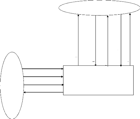
4.4.4 Context diagram
Is a diagram that represents the actors outside a system that
could interact with that system, This diagram is the highest level view of a
system, similar to Block diagram, showing a possibly software-based, system as
a whole and its inputs and outputs from/ to external factors.
In our case, external entities are the Expatriate who will
need the various services from the system, and the Employee who will request
the reports.
.. From Expatriate to the system: the system will provide
information using online system and Expatriate will login to access it without
changing anything and Expatriate choose a house to rent and validate, the
system accept or refuse, when the system accept it send to him a confirmation
message, the system send also a message to Employee and to the owner of the
house to inform them that a house got a client in order to proceed whit
contract and payment process which will be out of the system.
.. From Employee to the system: employee register information
to the system and the system provide him the confirmation.
25
The detail information is presented in context diagram below:
Services information
Employee information
House information
Confirm
Home Rental and Relocation Services System
Employee
House information
Expatriate
Expatriate registration
Confirm expatriate regist rati o n
Search services
Services information
Figure 5: HRRSS Context diagram
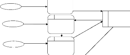
4.4.4.1 DFD level 0 for whole HRRSS
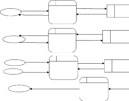
Figure 6: DFD level 0 for whole HRRSS
Employee
Expatriate
Employee
Employee
Report
Employee
Employee Information
Confirm information
Confirm Services
Services Information
House Information
House Rent
2.0 HRRSS
Services
Management
1.0 HRRSS
User
Management
3.0 HRRSS
House rent
Management
Employee Information
Employee Information
Services Information
Services information
House rent Info
House Information
4.0 HRRSS
Report
Management
D2
D3
D1
Service details
House details
User details
Remove user Info
User
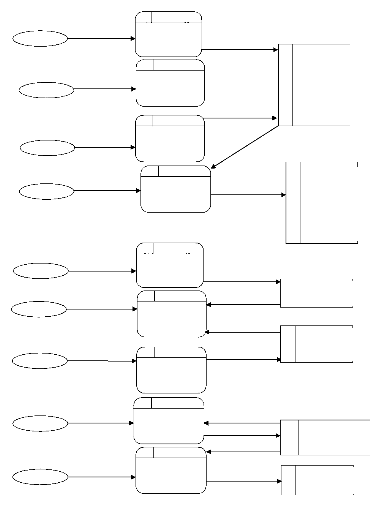
4.4.4.2 DFD Level 1 for User Management
1.1.1 HRRSS
User
Update user
User Info retrieved
Update
D
1
User details
1.3.1 HRRSS
1.2.1 HRRSS
Registration
Search
User Info saved
User Info retrieved
User Info updated
User Information
User
User services
User
|
User Info removed
|
D
4
|
Archive info
|
|
|
|
|
|
1.4.1 HRRSS
Archive
26
Figure 8: DFD Level 1 for User Management
Service Information
Employee
Registration
Search services
Expatriate
Search
D
2
Services details
D
4
Archive info
D
3
D
5
Renting info
D
3
House details
D
4
Archive info
2.3.1 HRRSS
Update
2.4.1 HRRSS
Update Service
Employee
Archive
Figure 9:DFD Level 1 for Service Management
Services Info updated
Service Info retrieved
House Info retrieved
Employee
Remove service Info
3.2.1 HRRSS
House availability
Service Info saved
4.4.4.3 DFD Level 1 for Service Management
2.1.1 HRRSS
2.2.1 HRRSS
Service Info removed
4.4.4.4 DFD Level 1 for House Management
3.1.1 HRRSS
House Information
Employee
Registration
House Info saved
Retrieve renting
Renting Info
3.3.1 HRRSS
Renting
3.4.1 HRRSS
Rent a house
Expatriate
Update house Info
Employee
Update
House Info
House Info
Remove house
Employee
House Info
Archive
House Info
3.5.1 HRRSS
Expatriate
Check house
House details
28
4.5 WAYS OF RECORDING INFORMATION
The information will be recorded in Mysql database. A database
contains different parts which are used to record and manipulate information.
The following steps elaborate on the components and design of an ERDM.
4.5.1 Entity Relationship Diagram
An ERD is a specialized graphic that illustrates the
interrelationships between entities in a database. ERD often use symbols to
represent three different types of information. Boxes are commonly used to
represent entities. Diamonds are normally used to be solved while retaining its
essential features one-to-one relationships.
This type of relationship takes place when a single occurrence
of an entity is relationship to just one occurrence of a second entity.
The term entity is widely used in database circles and is used
to mean any distinguishable object that is to be represented in the database.
ERDM is based on a perception of a real world that consists of a collection of
basic object called entities and also of relationships among these objects.
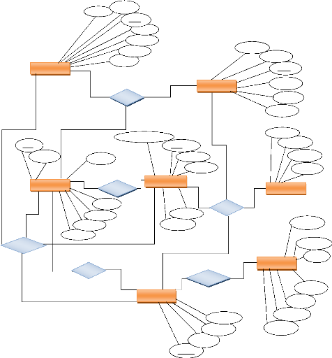
4.5.2 Designing the ERD
Entities are described in a database by set of attribute, like
the attribute username, password, telephone number, employee id and address
describe the entity, employees in the ERDM illustrated below. The primary key
employee id is used to uniquely identify an employees (since it may be possible
to have two employees with same name, surname, etc) the entity relationships
are shown in diamond shapes. The set of all entities of the same type and set
of all relationships of same type are termed as an entity set and relationship
set respectively, the overall logical structure (schema) of a database can be
expressed graphically by an ERD, which is built up from the following
components:
Rectangle: represent entity sets
Ellipse: represent attributes
Diamonds: represent relationship among entity sets Lines:
links attributes to entity sets and sets and entity sets to relationships Each
component is labeled with the entity or relationship that it represents.
29
4.5.3 Entity Relationship Diagram
REMOVE
ExId
LName
EMPLOYEE
EXPATRIATES
1-1
1-1
DOB
Sex
1-1
1-N
REN
FNam
Phones
FName
email
LOCATE
email
LNam
EmpI
WORK
Phones
Club of language
1-1 1-1
DOB
1-N
Sex
HOUSES
SERVICES
School
SerId
Hospital
1-1
Web list
Name
HouId
1-N
1-1
Market
POSSESS
ORGANIZATION
Price
Rooms
1-1
HAS
Website
1-N
1-N
OWNER
POBox
LOCATIONS
FName
Phones
Region
Name
OrgId
email
LName
District
Street LocId
email
OwId
DOB
Phones
Sex
Figure 12: Entity Relationship Diagram for HRRSS
30
4.6 CONCEPTUAL MODEL OF DATA
CMD has for goal to write under a formal way data that will be
used by the management information system. It is exactly a representation of
data, easily comprehensible, permitting to describe the system of information
by use of entities. This diagram permits to represent the structure of the
system of information for the data; this means the dependences or the relations
between different data.
The intervening elements in the modeling of the conceptual model
of data are:
Entity: an entity is the representation of a
material or immaterial element having a role in the system that is to be
described.
Attribute: An attribute is a characteristic of an entity that we
want to record or retrieve later. Data : A data is the element
of an entity. It is the most important element of database. Identifier:
is a set of properties (one or several) permitting to designate one
and a unique entity; it is a particular property of an object as there can't
exists two occurrences of this object for which this property could take the
same value.
Association: It makes possible to connect one
or more entities. These connections are stated via management rules. Contrary
to the entity, association is named with a verb. There are different
association's types.
Cardinalities: Cardinalities are a couple of values (minimum,
maximum).
The minimum cardinality corresponds to the minimal number of
times that each entity occurrence takes part in the association occurrences. It
generally takes values 0 or 1. The maximum cardinality corresponds to the
maximum number of times where each occurrence of the entity takes part in the
occurrences of association. It is at least equal to 1. The infinite one is
noted «N».
|
Cardinality
|
Signification
|
|
1,1
|
One-to-one
|
|
1,N
|
One-to-many
|
Table 1: Cardinalities
31
4.7 LOGICAL DATA MODEL
Logical data models represent the abstract structure of some
domain of information it will Includes all entities (tables), attributes
(columns/fields) and relationships (keys) , Is independent of technology
(platform, DBMS), Is normalized to fourth normal form (4NF) used in development
of this system.
1. ORGANIZATIONS (OrgId, Names, email, website,
POBox, Phones, LocId);
2. EMPLOYEES (EmpId, LName, FName, Sex, DOB,
Phones, email, OrgId );
3. LOCATIONS (LocId, Street, Region,
District);
4. LOCATE (LoId, ExId, SerId);
5. EXPATRIATES (ExId, LName, FName, Sex, DOB,
Phones, email, OrgId, HouId);
6. OWNERS (OwId, FName, LName, DOB, Sex, email,
Phones);
7. HOUSES (HouId, Names, Price, Rooms, OwId,
LocId, ExId);
8. SERVICES (SerId, HosId, CluId, MarId, SchId,
CluId, LocId).
9. MARKETS(MarId, Names, email, POBox, Phones,
SerId);
10. SCHOOLS(SchId, Names, email, POBox, Phones,
SerId);
11. HOSPITALS(HosId, Names, email, POBox,
Phones, SerId);
12. CLUBS(CluId, Names, email, POBox, Phones,
SerId);
13. WEBLIST(weId,Job title, Company, Link,
SerId);
14. LOGIN (LogId, Uname, Pword,
Ftion);
15. ARCHIVE (ArcId, SerId, HouId,
EmpId,ExpId).
4.8 THE CONCEPTUAL LEVEL 4.8.1 The Treatment Conceptual
Model
The conceptual model of treatment permits to treat the
dynamism of the information system, it means that operations are achieved
according to events. This model permits to represent schematic way the activity
of an information system without making reference to organizational choices or
the means of execution therefore. That is to say it allows defining what must
be done merely, but it doesn't say when, how, nor where.
32
The event
An event represents a change in the outside environment to the
information system; it can also represent a change in the information system
itself.

An external event is a change of the outside universe of the
information system
Symbol used:
An internal event is an internal change to the information
system

Symbol used: The Process A process is a subset of the activity of
the enterprise. It means that the activity of the enterprise is constituted of
a set of process. A process is itself composed of treatments regrouped in a set
named operations.
Symbols used:
The Operation
An operation is a set of actions executed by the system following
an event, or to a conjunction of events. This sets of actions are interrupted,
that means that the events are not taken so much into consideration, as long as
the operation has not yet been accomplished.
The synchronization
The synchronization of an operation defines a Boolean condition
on the contributive events having to trigger an operation. These are therefore
conditions at the level of events governed by a logical condition achieved by
the logical operations: EITHER, AND and NO.
4.8.2 Treatment Conceptual Model for House
information
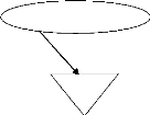
House information
Verification of information
Check house availability
Accept Reject
House available
House not available
33
Figure 13: Treatment Conceptual Model for House information
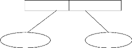
4.8.3 Treatment Conceptual Model for confirming
registration

Expatriate information
Verification of information
Check form

Complete information
Accept Reject
Figure 14: Treatment Conceptual Model for confirming
registration
34
4.8.4 Treatment Conceptual Model for services
information
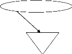
Services information
Select service
Service details
Get information

Show
Figure 15: Treatment Conceptual Model for services
information
4.9 DATA DICTIONARY
A data dictionary is a collection of descriptions of the data
objects or items in a data model for the benefit of programmers and others who
need to refer to them or the dictionary of data is at a time the pillar of work
and the result of research and analysis of data. It is just like a depicted
picture of the entire work. This dictionary of data defines all categories of
data or data types, brief the all essential information about the software is
included.
|
TABLE
|
FIELD
|
DESCRIPTION
|
TYPE
|
CONSTRAINTS
|
|
ORGANIZATIONS
|
OrgId
|
Identification of the Organizations
|
varchar(10)
|
Primary key
|
|
|
Names
|
Names of Organizations
|
varchar(120)
|
Not null
|
|
email
|
Email of the organizations
|
varchar(150)
|
Not null
|
|
website
|
Website of Organizations
|
varchar(120)
|
Not null
|
|
POBox
|
POBox of Organizations
|
varchar(15)
|
Not null
|
|
Phones
|
Phone numbers of Organizations
|
varchar(15)
|
Not null
|
|
LocId
|
Identification of Locations
|
varchar(10)
|
Foreign key
|
|
EMPLOYEES
|
EmId
|
Identification of Employees
|
varchar(10)
|
Primary key
|
|
LName
|
Last Name of Employees
|
varchar(120)
|
Not null
|
|
FName
|
First Name of Employees
|
varchar(100)
|
Not null
|
|
Sex
|
Sex of Employees
|
varchar(1)
|
Not null
|
35
|
DOB
|
Birth date of Employees
|
date
|
Null
|
|
Phones
|
Phone numbers of Employees
|
varchar(15)
|
Null
|
|
email
|
Email of Employees
|
varchar(150)
|
Null
|
|
OrgId
|
Identification of the Organizations
|
varchar(10)
|
Foreign key
|
|
LOCATIONS
|
LocId
|
Identification of Locations
|
varchar(10)
|
Primary key
|
|
Street
|
Street of Locations
|
varchar(120)
|
Not null
|
|
Region
|
Region of Locations
|
varchar(150)
|
Not null
|
|
District
|
District of Locations
|
varchar(120)
|
Not null
|
|
LOCATE
|
LoId
|
Identification of Locate
|
varchar(10)
|
Primary key
|
|
ExId
|
Identification of Expatriates
|
varchar(10)
|
Foreign key
|
|
SerId
|
Identification of Hospitals
|
varchar(10)
|
Foreign key
|
|
EXPATRIATES
|
ExId
|
Identification of Expatriates
|
varchar(10)
|
Primary key
|
|
LName
|
Last name of Expatriates
|
varchar(120)
|
Not null
|
|
FName
|
First of Expatriates
|
varchar(150)
|
Not null
|
|
Sex
|
The sex of Expatriates
|
varchar(1)
|
Null
|
|
DOB
|
The birth date of Expatriates
|
date
|
Null
|
|
Phones
|
Phone numbers of Expatriates
|
varchar(15)
|
Not null
|
|
email
|
Email of Expatriates
|
varchar(150)
|
Not null
|
|
OrgId
|
Identification of the Organizations
|
varchar(10)
|
Foreign key
|
|
OWNERS
|
OwId
|
Identification of the owners
|
varchar(10)
|
Primary key
|
|
FName
|
First Name of the owners
|
varchar(120)
|
Not null
|
|
LName
|
Last Name of the owners
|
varchar(150)
|
Not null
|
|
DOB
|
The birth date of the owners
|
date
|
Null
|
|
Sex
|
The sex of the owners
|
varchar(1)
|
Null
|
|
email
|
The Email of the owners
|
varchar(120)
|
Not null
|
|
Phones
|
Phone numbers of the owners
|
varchar(15)
|
Not null
|
|
HOUSES
|
HouId
|
Identification of the houses
|
varchar(10)
|
Primary key
|
|
Names
|
Names of the houses
|
varchar(120)
|
Not null
|
|
Price
|
The price of the houses
|
varchar(15)
|
Not null
|
|
Rooms
|
Rooms that the house has
|
int(11)
|
Not null
|
|
OwId
|
Identification of the owners
|
varchar(10)
|
Foreign key
|
|
LocId
|
Identification of Locations
|
varchar(10)
|
Foreign key
|
|
SERVICES
|
SerId
|
Identification of the services
|
varchar(10)
|
Primary key
|
|
Hospital
|
Services about hospital
|
varchar(120)
|
Not null
|
|
Club of language
|
Services about club of language
|
varchar(120)
|
Not null
|
|
Market
|
Services about market
|
varchar(120)
|
Not null
|
|
School
|
Services about school
|
varchar(120)
|
Not null
|
|
Web list
|
Services about web list
|
varchar(120)
|
Not null
|
|
LocId
|
Identification of Locations
|
varchar(10)
|
Foreign key
|
|
MARKET
|
MarId
|
Identification of the market
|
varchar(10)
|
Primary key
|
|
Name
|
Name of market
|
varchar(120)
|
Not null
|
|
Email
|
email of market
|
varchar(15)
|
Not null
|
|
Pobox
|
Pobox of market
|
varchar(15)
|
Not null
|
|
Phone
|
phone of market
|
varchar(15)
|
Not null
|
|
SerId
|
Identification of Locations
|
varchar(15)
|
Foreign key
|
|
SCHOOL
|
SchId
|
Identification of the school
|
varchar(10)
|
Primary key
|
36
|
Name
|
Name of school
|
varchar(120)
|
Not null
|
|
Email
|
email of school
|
varchar(15)
|
Not null
|
|
Pobox
|
Pobox of school
|
varchar(15)
|
Not null
|
|
Phone
|
phone of school
|
varchar(15)
|
Not null
|
|
SerId
|
Identification of Locations
|
varchar(15)
|
Foreign key
|
|
CLUB
|
ClId
|
Identification of the Club
|
varchar(10)
|
Primary key
|
|
Name
|
Name of Club
|
varchar(120)
|
Not null
|
|
Email
|
email of Club
|
varchar(15)
|
Null
|
|
Pobox
|
Pobox of Club
|
varchar(15)
|
Not null
|
|
Phone
|
phone of Club
|
varchar(15)
|
Not null
|
|
SerId
|
Identification of Locations
|
varchar(15)
|
Foreign key
|
|
HOSPITAL
|
HosId
|
Identification of the Hospital
|
varchar(10)
|
Primary key
|
|
Name
|
Name of Hospital
|
varchar(120)
|
Not null
|
|
Email
|
email of Hospital
|
varchar(15)
|
Null
|
|
Pobox
|
Pobox of Hospital
|
varchar(15)
|
Not null
|
|
Phone
|
phone of Hospital
|
varchar(15)
|
Not null
|
|
SerId
|
Identification of Locations
|
varchar(15)
|
Foreign key
|
|
WEBLIST
|
WeId
|
Identification of the Weblist
|
varchar(10)
|
Primary key
|
|
Job
|
Name of job
|
varchar(120)
|
Not null
|
|
Company
|
Name the company
|
varchar(150)
|
Not null
|
|
Link
|
Website that provide more information
|
varchar(100)
|
Not null
|
|
SerId
|
Identification of Locations
|
varchar(15)
|
Foreign key
|
|
LOGIN
|
LogId
|
Identification of Login
|
varchar(10)
|
Primary key
|
|
Uname
|
User name for login
|
varchar(120)
|
Not null
|
|
Pword
|
Password for login
|
varchar(150)
|
Not null
|
|
Ftion
|
User function
|
varchar(150)
|
Not null
|
|
ARCHIVES
|
ArchId
|
Identification of Archive
|
varchar(15)
|
Primary key
|
|
SerId
|
Identification of Services
|
varchar(15)
|
Null
|
|
HouId
|
Identification of Houses
|
varchar(15)
|
Null
|
|
EmpId
|
Identification of Employees
|
varchar(15)
|
Null
|
|
ExpId
|
Identification of Expatriates
|
varchar(15)
|
Null
|
Table 2: HRRSS Data dictionary
4.10 ORGANIZATIONAL MODEL OF PROCESS
The diagram shown below is there to represent OMP that is to be
done in the system. It seems there for describing properties of untreated data
of processes that had not been treated by the Conceptual Model of
Processes.
Task: Group of elementary operations executed
within a functional procedure (phase of execution).
C: Computerized M: Manual
37
Period
|
Process
|
Nature
|
Workstation
|
|
Place
|
Actor
|
Resource
|
|
When Expatriate make registration
|
|
C
|
Anywhere with internet connection
|
Expatriate
|
Computer
|
|
|
|
|
|
|
|
|
|
|
|
|
|
When
Expatriate rent a house
|
|
C
|
Anywhere with internet connection
|
Expatriate
|
Computer
|
|
|
|
|
|
|
|
|
|
|
|
38
When Expatriate search services
|
|
C
|
Anywhere with internet connection
|
Expatriate
|
Computer
|
|
|
|
|
|
Table 3: Organizational Model of Process
4.11 PHYSICAL DATA MODEL
The PDM is used to design the internal schema of a database,
depicting the data tables (derived from the logical data entries), the data
columns of those tables (derived from the entity attributes), and the
relationships between the tables (derived from the entity relationships). The
features of the physical model of data include:
+ Specification of all the tables and columns.
+ Foreign keys are used to identify relationship between
tables.
+ Physical considerations may cause the physical model of data
to be quite different from the logical model of data.
At this level, the data modeler will specify how the logical
data model will be implemented in the database schema. The steps for physical
data model design are as follows:
+ Convert entities into tables.
+ Convert attributes into columns.
+ Modify the physical model of data based on physical
constraints.
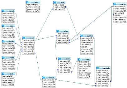
39
Figure 16: Physical Data Model
4.12 ADVANTAGE OF THE NEW SYSTEM
The HRRSS for international organizations is developed to
support the existing system which presents some deficiencies. This new system
will help to reduce the imperfection of Expatriates or new coming within
international organizations by replacing the existing system in order to
benefit the advantage of information technology in better management of
international organizations.
40
CHAPTER FIVE: IMPLEMENTATION OF THE NEW
SYSTEM
5.1INTRODUCTION
The fifth chapter putting a planned system into action and
examine in details the analysis and design of the Home Rental and Relocation
Services system in Kigali. The present chapter discusses the implementation of
the system, highlighting the testing exercise and describing some of the main
components of the system's Graphical User Interface. It will give an output
from programming language and other tools used to develop our system.
5.2 System Design
User interface design is the overall process of designing the
interaction between a human (user) and machine (computer).it includes graphic
design, information design and a wide variety of usability methods.
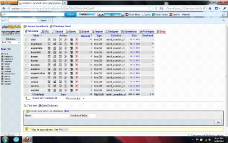
Figure 17: HRRSS database
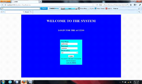
Figure 18: HRRSS login form with data
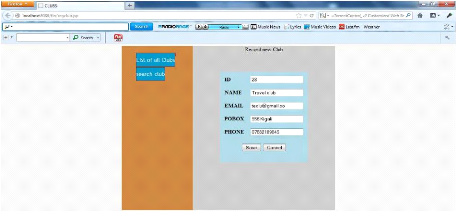
41
Figure 19: Rcord of services(Club of language teach)
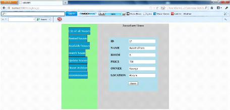

Figure 20: HRRSS House information record
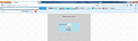
42
Figure 21: Form for checking details of any service
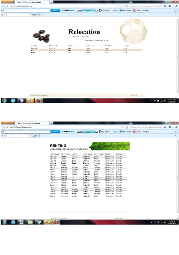
Figure 22: Report of house and services on a location
Figure 23: Report of Expatriate, house and owner on a location
43
44
5.3 The system implementation
To implement this project, one server and one or more clients
connected over the same network are needed. A server, on which a server program
is running, handles and processes all clients' requests before it communicates
with the MySQL server (5.0 versions) to store or retrieve information requested
by the client machine. Without this middle server, no communication can occur
between the MySQL server and the client Machine. The middle server and the
MySQL server are started before the client program is started.
5 .4 Verification of Hypothesis
The hypothesis of this project is, «It is possible to offer
effective and efficient information regarding house for rent and relocation
services in Kigali by developing an online application that can reduce the time
spend and stress that affect expatriate, employees and people who can be
involved in its findings by international organizations».
According to the above hypothesis, online booking are developed
successfully.
The user is able to search house by selecting location and view
it, to view available houses in desired location by clicking on it, expatriate
is also able to make a booking of a desired house. The Employee is able to use
this application to manage booking list and delete the old booking requests; if
there is a change he/she can inform the Expatriate by sending him a message
through the system. This application allows the manager to make a regular
report.
45
CHAPTER SIX: FUTURE ENHANCEMENT
6.1 CONCLUSION
The main objective of this project was to improve the existing
property services and to provide a solution to the problems encountered in
international organizations' services sector regarding the way home are rented
and the way relocation services and related information are provided to
expatriates or new coming people in Kigali.
This objective has been achieved successfully with the best
practices in designing and building of a web based application for home rental
and relocation services.
The web based application for home rental and relocation service
system has been designed using Java server pages as programming language,
apache server and Mysql database.
Therefore, the home rental and relocation service system built
came up with various features such as:
· Browsing all active houses for rent.
· Locate services
· Searching houses
· Booking houses
· Adding houses and services
This work shows that a home rental and relocation service system
can really help people and organizations to offer good quality of service in
renting houses and relocations.
6.2 RECOMMENDATION
+ For further research, we are suggesting to add the following
modules in HRRSS.
- Module of online payment in new system using SIMTEL electronic
card.
- Google map in order to improve functionality.
+ We advise people or company to include the above listed module
in order to make this
product full working software that can be implemented in a
professional environment.
46
REFERENCES
BOOKS AND PUBLICATIONS
1. David M. KROENKE, Database processing fundamental
design and implementation, 6th edition, Prentice Hall, 2006.
2. PANKAJ JALOTE, An integrated approach to software
engineering, 2nd edition, by Narosa publishing house,
1997.
3. Fred R. Mc Faddens, Jeffrey A.hoffer, mary B.PrescoTt,
Modern Database Management, 6th edition, Prentice
Hall, 2002.
DOCUMENT AND REPORT
1. NTAWUMENYIKIZABA Abdalh, Online Application for
Residential Information System, NUR, 2011.
2. KWIZERA Hilaire, Management System of Rooms and
Restaurant, INILAK, 2011.
ELECTRONIC REFERENCES
1.
http://www.kenorrinst.com/dwpaper.htmls,2012/80/22.
2.
www.webbasedprogramming.com
2012/80/22.
3.
http://www.samsvb.co.uk/index.php?page=lesson&les=Lesson%2014,
2012/80/22.
4.
condor.depaul.edu/jpetlick/extra/394/Session2.ppt
, 2012/80/22.
5.
http://en.wikipedia.org/wiki/Software_testing,
2012/80/22.
6.
http://en.wikipedia.org/wiki/Software_maintenance,
2012/80/22.
7.
http://en.wikipedia.org/wiki/Data_flow_diagram,
2012/80/22.
47
APPENDIES
APPENDIX 1: OARIS-DFD level zero

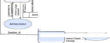
Operation request
peration accept
House infos saved
oDerties
|
Location info's displayed
|
2.0 OARIS visit
|
|
|
Location file
|
|
|
|
|
|
|
|
|
|
7-5.0 OARIS House
operations

Search House request
aN N_ Q
v s 2
OARIS
Enter house infos
o
House infos
Request House infc·" 1 .0
C C
O
O
U o
J
Searching propert
Display available
House
Q aeration
|
Administrator
|
|
|
|
|
|
|
|
|
|
|
|
|
|
|
4.0 OARIS login
|
House info file House info
A-1--House info's save
Enter house infos I
request
cation reque
U
E--
et location Booking accept
V
Booking file
3.0 OARIS
booking
ookinq reque
Booking accept
Booking request
st
OARIS
Close session request
6.0


logout
Figure 24: OARIS-DFD level zero
A
APPENDIX 2: ERD-Management System of Rooms and
Restaurant
B
Figure 25: ERD-Management System of Rooms and
Restaurant
| 

