CHAP 5 SIMULATION USING MATLAB
5.1 Analysis and Simulation on array antenna
This section will be exploring the radiation patterns of a
planar array by varying various parameters. The parameters include the
inter-element spacing, number of elements in the array and the amplitude
distribution. The subsequent simulations on planar array are performed using
the MATLAB 6.5.1. The element polarization is assumed to be in the x-
plane.
Appendix provides the MATLAB code we used.
5.1.1 Variation of number of elements
N
The following assumptions are made for the investigation:
§ Normalized inter-element spacing = 0.5
§ Side lobe level = 20dB
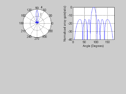
. Fig 5.1, Fig 5.2 and Fig.5.3 illustrate the plot generated
from MATLAB
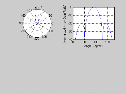
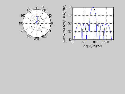
Fig 5.1
: Radiation pattern with 4 elements
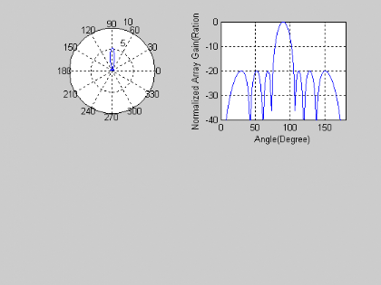
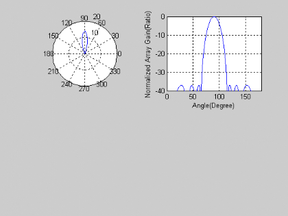
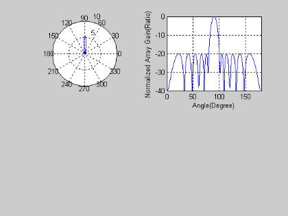
Fig 5.2
Radiation pattern with 8 elements
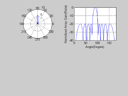
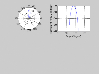
Fig 5.3
: Radiation pattern with 10 elements
Observed results are tabulated in Table 1
|
Number of elements
|
Remarks
|
|
2
|
Main Beam with no side lobe
|
|
4
|
2sidelobes appear
|
|
6
|
4sidelobes appear
|
|
8
|
6sidelobes appear
|
|
10
|
8sidelobes appear
|
Table 1 :Results of varying number
of elements
5.1.2 Variation of Side Lobe Level
The following assumptions are made for the synthesis:
§ Normalized inter-element spacing = 0.5
§ Number of elements = 8
Plot generated from MATLAB are following
Fig
5.4: Radiation pattern with 5dB.
Fig
5.5: Radiation pattern with 15dB
Fig
5.6: Radiation pattern with 37dB
Fig
5.7: Radiation pattern with 40dB
Observed results are tabulated in Table 2.
|
Side lobe level(dB)
|
Remarks
|
|
5
|
6 side lobes appear
|
|
10
|
6 side lobes appear
|
|
15
|
6 side lobes appear
|
|
20
|
6 side lobes appear
|
|
25
|
6 side lobes appear
|
|
30
|
6 side lobes appear
|
|
40
|
6 side lobes appear
|
Table 2: Results of varying side
lobe level
5.1.3 Variation of Inter-element
Spacing.
This section will be analyzing on the radiation pattern for
various inter-element spacing.
First and foremost, the following assumption is made:
§ Side lobe level = 20dB
§ Number of elements =8
The data obtained was tabulated in Table 3
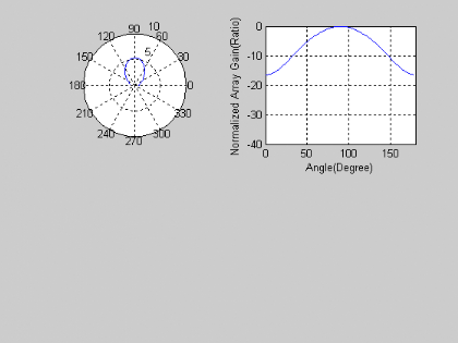
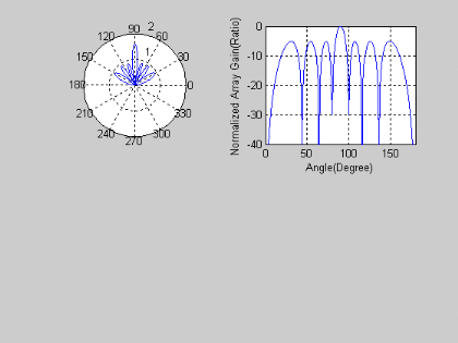
Fig 5.8
Radiation Pattern with normalized inter-element spacing of 0.125
Fig
5.9: Radiation Pattern with normalized inter-element spacing of 0.5
Fig
5.10: Radiation Pattern with normalized inter- element spacing of 0.75
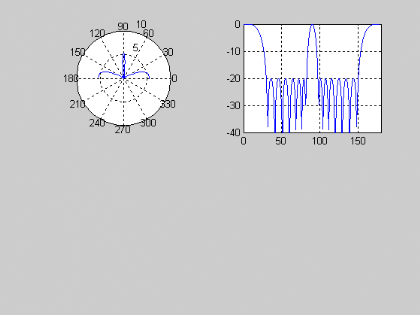
Fig 5.11 Radiation Pattern with
normalized inter-element spacing of 1
Observed results are tabulated below.
|
Number of elements
|
Inter-element spacing(Normalized)
|
Remarks
|
|
8
|
0.125
|
Main Beam with no side lobe
|
|
8
|
0.25
|
2 side lobes appear
|
|
8
|
0.375
|
6 side lobes appear
|
|
8
|
0.5
|
6sidelobes appear
|
|
8
|
0.625
|
8sidelobes appear
|
|
8
|
0.75
|
10sidelobes appear
|
|
8
|
0.825
|
14sidelobes appear
|
|
8
|
1
|
2grating lobes and12 side lobes appear
|
Table 3 : Results of varying
inter-element spacing
| 

