Bibliographie
[1]: L.Stoyanov,G.Notton et V.Lazarov «Optimisation des
systèmes multi sources de production d'électricité
à énergie renouvelables » Revue des énergies
renouvelables Avril 2007, V10 N°1 .
[2]: A.Zaatri and T. Kerbach «Design of PWM DC-DC
converter dedicated to a photovoltaic system » Seventh World Renewable
Energy Congress (WREC VII).22 June -5 July 2002 Cologne- Germany.
[3]: M.E.M- Brahimi « Situation des énergies
renouvelables en Algérie » Conférence sur la maîtrise
de l'énergie et de l'environnement dans un contexte d'économie.
Mai 2001.
[4]: F.youcef .Ettoumi, L.nacet, A. Adane, H. Sauvageot «
Génération du Gisement Quotidien en Algérie »
3ème Séminaire National en Génie électrique 29.31
PP25 1, 256, 2001.
[5]: A.Mefti, H.Mimouni « Evaluation du potentiel
énergétique solaire » Bulletin des énergies
renouvelables No 2, Décembre 2002.
[6]: Pascal. Pernet « Développement de cellules
solaires en Silicium amorphie de type `n.i.p' sur substrats souples »
Ecole Polytechnique Fédérale de Lausanne (EPFL), Thèse
n° :2303, 2000.
[7]: « Energie Photovoltaïque » Guide des
Energies Renouvelables 2002.
[8]: Saadi. A « Etude comparative entre les techniques
d'optimisation des systèmes de pompage photovoltaïque »
mémoire de magistère, université Med Khider Biskra, juin
2001.
[9]: Jean-Paul Braun, Benjamin Faraggi, Anne Labouret «Les
cellules solaires » ETSF, paris, 1996
[10]: A. Midoun, A. Daoud «Commande Floue de la Charge
d'une Batterie dans une Installation Photovoltaïque» Rev. Energ.
Ren.: ICPWE (2003) 67-72.
[11]: James P. Dunlop: « Recommendation For Maximising
Battery Life In Photovoltaic Systems » Proceedings of Forum 2001, Solar
Energy: The Power to Choose, April 2 1-25, 2001
[12]: James P. Dunlop, P.E. « Batteries and Charge Control
In Stand-Alone Photovoltaic Systems » Fundamentals and Application,
January 15, 1997. Florida Solar Energy Centre.
[13]: Jean. Hladik « Accumulateurs électriques
». Paris 1977.
[14]: Department of energy Handbook 1084-95 « Primer on
lead Acid storage batteries »September 1995.
[15]: Laszlo. Balogh « Implementing Multi-State Charge
Algorithm with the UC3 909 Switch mode Lead-Acid Battery Charger Controller
», U-155 Application Note, Unitrode Product & Applications Handbook,
1997, pp. 3-488 -3-5 16.
78
[16]: Eric P. Usher and Michael M.D. Ross «Recommended
practices for charge controllers» Report IEA PVPS T3-05:1998.
[17]: Albert Paul Malvino « Principe d'électronique,
cours et exercices corrigés » 6ème édition Dunod,
Paris, 2002.
[18]: A.N 1014 « Designing a power supply » Mars 27,
2002.
[19]: J.P. Ferrieux, F.Forest « Alimentation à
découpage, Convertisseurs à résonance, principes,
composants, modélisation » Edition Dunod. 1999, ISBN 2 10 004137
1.
[20]: L .Timothy. Skvarenina « The Power Electronics
Handbook », Edition J. David Irwin, Auburn University, CRC Press 2002,
chap. 8.
[21]: Harsono. Hadi « Photovoltaic water pump-system »
August, 2003.
[22]: Bigonoff « La programmation des PIC par
Bigonoff». Seconde partie (PIC16F876- 16F877), 7ème
Révision, 2003.
[23]: A. Oumnad « Microcontrôleurs : le PIC 1 6F876/1
6F877 ».
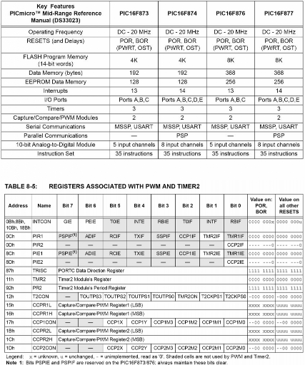
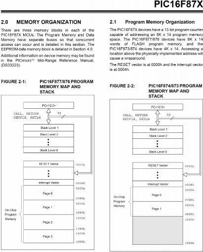
[24]: Datasheet « PIC 1 6F87x: 28/40 pin CMOS Flash
Microcontrollers » . 1999 Microchip Technology Inc. DS30292B
[25]: Olivier Dartois-Jacques Duprat
«Microcontrôleurs Pic-Présentation et Méthode de
Programmation ».
[26]: A. John « Simple Switch mode lead-acid Battery
charger» U-131 Application Note, Unitrode Product & Applications
Handbook, 1997, pp. 3-226 - 3-234.
[27]: Wilk. H «Inverters for photovoltaic systems »
Comett-Book, Fraunhofer-ISE, Freiburg, Germany, 1995.
[28]: Frederick. M, Ishengoma, Lars. E. Nokum «Design and
implementation of a digitally, controlled stand-alone photovoltaic power
supply».Nordic Workshop on Power and Industrial Electronics, NORPIE/2002,
12 -14 August 2002, Stockholm, Sweden.
[29]: S. Harrington « Battery charge controller
characteristics in photovoltaic systems» IEEE AES MAGAZINE August 1992.
[30] : N. Achaibou, A. Malek et N. Bacha
« Modélisation de Batterie au Plomb Acide Dans un Système
Photovoltaïque », 1er Séminaire sur la Contribution de
l'Energie Solaire et Eolienne Dans le Développement Durable Addrar,
Octobre 2001.
[31] : Christain Tavernier, « Application
Industrielles des Pics » Collection EEA série Technologie
électronique, Dunod 2001.
[32]: Bigonoff « La programmation des Pics »
1ère partie PIC16F84 - 6ème Révision 2002.
[33]: B.Zoller « Pc et Electronique Pratique » +
CD-ROOM, Micro Application ,1999 .
79
[34]: Pascal Mayeux «Apprendre la programmation des PIC,par
l'expérimentation et la simulation » plus un CD-ROOM, ETSF
2ème édition 2002.
[35]: Hartono Darmawaskita « DC/DC Converter Controller
using a PICmicro® microcontroller » 2000 Microchip Technology Inc.
DS00216A.
[36]: Michel Capderou « Atlas solaire de l'Algérie
» O P U, Alger, 1988.
[37]: Steven .J. Strong and William « The Solar Electric
House » 1993.
[38]: Walker, Geoff R. « Evaluating MPPT converter
topologies using a MATLAB PV Model » Australasian Universities Power
Engineering Conference, AUPEC `00, Brisbane, 2000.
[39]: Dan butler« Lead-acid battery charger Implementation
Using pic14C00 » 1997, Microchip Technology. Inc DS00626A.
[40]: Lasnier. France. Ang Tonygan « Photovoltaic
Engineering Hand book » 1990.
[41]: EE362L, Power Electronics, « DC-DC Buck Converter
» Version February 28, 2006.
80
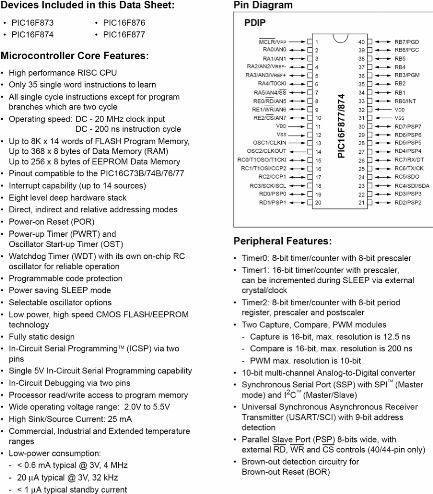
Annexe
Annexe
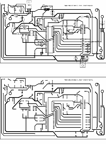
Circuit imprimé : Coté composants
Circuit imprimé : Coté liaisons
81


82
83
84

85

86
87
88
89
90
91


92


93

94

95
What is MPLAB PM3?
The MPLAB PM3 is a Microchip microcontroller device
programmer. Through interchangeable programming socket modules, MPLAB PM3
enables you, to quickly and easily program the entire line of Microchip
microcontroller devices.
MPLAB PM3 may be used with MPLAB IDE running under supported
Windows OS's (see "Readme for MPLAB PM3 . txt" file for support list) or as a
stand-alone programmer.
What MPLAB PM3 Does
MPLAB PM3 can be set up on the serial (COM 1-4) or USB
communications port on your PC. With MPLAB PM3 you can perform the following
operations:
· Program memory, configuration bits, EEPROM data memory,
ID locations and calibration data into devices.
· Program devices using ICSPTM (In-Circuit Serial
ProgrammingTM) on the target board and user GO, PASS and FAIL signals to
interface with the MPLAB PM3.
· Verify that microcontrollers are blank.
· Verify that code in the target microcontroller matches
your firmware.
· Read code from an unprotected microcontroller into the
MPLAB IDE's program memory window for debugging and programming into other
devices.
· Program unique serialized ID numbers into your firmware
using Serial Quick Turn Programming (SQTPSM) files.
· Store environments on an MPLAB PM3 Card.
MPLAB PM3 System Components
The MPLAB PM3 device programmer system consists of the
following:
· MPLAB PM3 device programmer
· Module sockets
· RS-232 Interface cable to connect to any standard PC
serial port
· USB Interface cable to connect to any standard PC USB
port
· ICSP cable
· Power supply
· MPLAB IDE software - an Integrated Development
Environment including a text editor, project manager and simulator for
debugging. Also included are the MPASM assembler, MPLINK object linker and
MPLIB object librarian.
How MPLAB PM3 Helps You
With the MPLAB PM3 device programmer, you can program Microchip
devices from a PC Host, or you can use the device programmer as a stand-alone
unit.
· MPLAB PM3 is easy to use and flexible in programming
Microchip devices and package types.
96
· MPLAB PM3 will expand to support future Microchip
devices always providing the latest programming algorithms to support Microchip
PIC microcontroller devices and other Microchip parts, via the Microchip web
site (
http://www.microchip.com).
· With an optional MPLAB PM3 Card inserted, you can store
and transport device settings for programming.
Installing MPLAB PM3 Hardware
The MPLAB PM3 hardware is simple to set up:
· If you are using MPLAB IDE:
o Attach the communications cable.
o Connect the power supply to the MPLAB PM3.
o Install the socket module (or attach the ICSP cable).
· If you are using MPLAB PM3 in stand-alone: o Connect
the power supply to the MPLAB PM3.
Installing the Communications Cable
MPLAB PM3 provides communications with the host PC via an RS-232
9-pin D type connector or a USB connector.
MPLAB PM3 is supplied with two 6-foot data cables: one with
DB-9 connectors and one with USB connectors. All lines on the serial cable are
wired straight through. The serial cable is NOT a null modem cable.
Installing a Socket Module or ICSP Cable
Socket modules are sold separately. The MPLAB PM3 comes with an
18-inch ICSP cable for ICSP programming.
Socket Module Installation
Socket modules are available to accommodate each device
package. The Product Selector Guide (DS00 148) lists Microchip's
devices, tools and socket modules. The Development System Ordering
Guide (DS30 177) describes the available socket modules.
For MPLAB PM3 Socket Modules
1. Align the connectors on the socket module with the connectors
on the MPLAB PM3.
2. Push the socket module down evenly mating the connectors.
It is always a good practice to insert a known blank device and
do a blank check whenever the socket module is changed.
ICSP Cable Installation
1. Connect the ICSP cable connector to the ICSP socket on the
MPLAB PM3.
2. Leave the individual leads unconnected at this time..
97
98
99

100
|
Description
|
Type of power
supply
|
Architecture
|
|
The input voltage is converted
into a lower output
voltage.
|
Buck Converter
|
|
|
|
|
|
|
|
|
|
|
|
|
|
|
|
|
|
The input voltage is converted
into a higher output
voltage.
|
Boost converter
|
|
|
|
|
|
|
|
|
|
The input voltage is converted
into a negative voltage.
|
Buck-Boost
converter
|
|
|
|
|
|
|
|
|
|
|
Several isolated output
voltages, up to approx. 250
are
possible.
|
Flyback converter
|
|
|
|
|
|
|
|
|
|
|
|
|
|
|
One electrically isolated
voltage, up to approx.
100
Watts.
|
Single Transistor
Forward converter
|
|
|
|
|
|
|
|
|
|
|
|
|
|
|
|
|
|
|
|
|
|
One electrically isolated
voltage, up to approx. 1 KW.
|
Two-Transistor
Forward converter
|
|
|
|
|
|
|
|
|
|
|
|
|
|
|
|
|
|
|
One electrically isolated
voltage, up to few KW.
|
Half-Bridge
Push-Pull
Converter
|
|
|
|
|
|
|
|
|
|
|
|
|
|
|
|
|
|
|
|
|
|
|
One electrically isolated
voltage, up to many KW.
|
Full-Bridge
Push-Pull
converter
|
|
|
|
|
|
|
|
|
|
|
|
|
|
|
|
|
Switch mode power supply for
sinusoidal mains current.
|
Power Factor Pre-
regulator (PFC)
|
|
|
|
|
|
|
101
Réalisation d'un régulateur solaire
à base de microcontrôleur pour le contrôle de l'état
de charge et la
protection des accumulateurs
| 

