Annexe 2
Annexe 3
|
Mots clés : Aéronautique. Norme RS232, SPARTAN3,
VHDL, Visual Basic.
Résumé : Durant ce projet. nous avons pu
effectué la mise au point de la procédure permettant de tester un
instrument de bord d'avion choisi d'avance. En premier lieu. on a
utilisé la carte SPARTAN-3 comme carte d'acquisition et en second lieu.
on a eu recours au logiciel Visual Basic pour concevoir l'interface graphique
de communication entre l'ordinateur et la carte d'acquisition.
|
|
Keys words: Aeroimutical. RS232 Nortn. SPARTAN3. VHDL. Visual
Basic,
Abstract: During this project. we made the procedure allowing
us to test an instrument of the front panel of the plane that had been chosen
before. First we used the SPARTAN3 as an acquisition card: secondly we realized
a graphical interface based on the software Visual Basic.
|
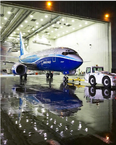
Initial Model 737s (-100/-200)
The Boeing 737 is the best-selling jetliner fleet in
the world. Much of the credit for this achievement belongs to the 737-200,
which accounted for 1,114 of all 737s ordered.
Initial Model 737s (-100/-200)
Unlike other early twinjets, the 737 featured engines
mounted in pods beneath the wings, making it easy to service.
Initial Model 737s (-100/-200)
The Beginning of the World's Most Popular Jet
Family
The first flight of the Boeing 737-100 occurred April
9, 1967. With pilots Brian Wygle and Lew Wallick at the controls, the airplane
took off from Boeing Field in Seattle and flew for 2-1/2 hours before landing
at Paine Field in Everett, Washington. The 737 was designed as a logical short-
range airplane to complement larger 707 and 727 jetliners. The 737 was
certified by the U.S. Federal Aviation Administration in December 1967 after
more than 1,300 hours of flight testing by a six-airplane fleet. For the first
time, certification included approval for automatic approaches in bad weather
under Category II conditions -- defined as 100-foot ceilings and 1,200-foot
forward visibility. The first 737-100 was delivered to Lufthansa December
28,1967, and began commercial revenue service on February 10, 1968. The last
737-100 model was produced in 1969 and delivered in November that same year.
Interestingly, the last 737-100 delivered was actually the first 737 Boeing
produced. The aircraft had been used by Boeing as a test airplane before being
delivered to NASA on July 26, 1973, for use as a test and training aircraft by
the space agency. Boeing delivered 30 737-100s.
Classic 737s (-300/-400/-500)
Entering service as deregulation made air travel
increasingly competitive, the 737-300 quickly rose to prominence for
hub-and-spoke and point-to-point operations

Classic 737s (-300/-400/-500)
As a replacement for 737-200s, the forward-looking
737-300 offered more seats, better performance and fuel economy, and much
lower noise.

Classic 737s (-300/-400/-500)
Airlines count on the 737's rapid turn-around: it
allows ground crews to handle passengers, luggage, food and beverages, and
clean-up quickly and easily, so that each plane can be scheduled for more
flights per day.

Classic 737s (-300/-400/-500)
The common flight deck of the pilot-centered 737-300,
-400, -500 incorporates digital technology like that on the 757/767 family.
These electronics systems provide concise flight information, which allows
increased fuel efficiency and reduces the crew's workload when landing the
airplane in bad weather.
Classic 737s (-300/-400/-500)
Offering 18 more seats than the 737-300 in typical 2-class
configurations, the 737-400 also offers charter and tour operators
seating for up to 168 passengers
Classic 737s (-300/-400/-500)
Together with the 737-300 and 737-500, the 737-400
delivered unmatched reliability.

Classic 737s (-300/-400/-500)
Although it has the largest model designator of its
generation, the 737-500 is actually smaller than either the 737-300 or
the 737-400.
Classic 737s (-300/-400/-500)
Designed as a family, all three models of the current
(second) generation of 737s are built simultaneously.
Classic 737s (-300/-400/-500)
Only 10 inches longer than the earlier 737-200, the
737-500 uses 20% less fuel and has the longest range capability of the
three models in the second-generation 737 family.
Boeing Launches New Higher Capacity, Longer Range
737
Boeing officially launched the 737-900ER following the
completion of a sales agreement for up to 60 airplanes to Indonesias first
low-cost carrier, Lion Air. The new 737-900ER, formerly the 737-900X, becomes
the newest member of the Next-Generation 737 family. The 737-900ER features
aerodynamic and structural design changes, which allows the derivative to
accommodate higher takeoff weights, carry 26 more passengers and fly farther
than the 737-900.
Boeing Unveils Next-Generation 737 with Dynamic 787
Livery
Boeing today unveiled in Seattle an Air Berlin
Next-Generation 737-700 carrying the dynamic blue and white livery previously
shown only on the all-new Boeing 787. This 737 will anchor marketing activities
involving Boeing and Air Berlin, details of which will be provided at the July
Farnborough Air Show, and allow Boeing to showcase the technologically advanced
Next-Generation 737 in an exciting way. Boeing painters used innovative
painting techniques from the automotive industry to create the unique color
scheme. Air Berlin takes delivery of the 737 later this month.
Next Generation 737s
(-600/-700/-800/-900)
The smallest member of the Next-Generation 737 airplane
family -- the 737-600 -- made its first flight today, with Boeing
Capts. Mike Carriker and Ray Craig at the airplane's controls. The 102-foot,
6-inch airplane took off from Renton Municipal Airport in Renton, Wash., at
10:16 a.m. PST. This newest 737 model, launched by Scandinavian Airlines (SAS),
is equivalent in size to the 737-500, and provides seating for 110 to 132
passengers.
Next-Generation 737s
(-600/-700/-800/-900)
Boeing employees in Renton, Wash., prepare to fasten wings of
the first Boeing 737-900 to the 124-foot-long (37.8 meter) body
section. The 737-900 is the longest of the Next-Generation 737s, and will be
able to seat up to 189 passengers in a one-class configuration. Next-Generation
737s are the newest, most advanced-design airplanes in their class, and feature
an improved wing design that allows the airplanes to fly higher than competing
Airbus A320 airplanes. A higher maximum cruising altitude means passengers can
enjoy a smoother ride and airlines benefit by being able to fly above bad
weather, congested routes and less capable airplanes.
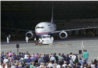
Next-Generation 737s (-600/-700/-800/-900) Champions:
Boeing 737-900 Makes World Premier
Symbolizing the spirit of launch customer Alaska Airlines,
Iditarod sled-dog race champion Doug Swingley and his team escort the first
Boeing Next-Generation 737-900 out of the factory for its world
premiere. Boeing and Alaska Airlines and employees cheered the airplane at a
rollout celebration in Renton, Wash. The Boeing 737-900 is the newest Boeing
commercial jetliner and the largest model in the Next-Generation 737
family.
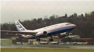
Next-Generation 737s
(-600/-700/-800/-900)
The first Boeing Next-Generation 737-900 takes off on
its maiden flight, heading over Lake Washington near Seattle. The flight, which
lasted three hours, marked the start of a six-month 737-900 flight-test
program. The 737-900, largest of the Next-Generation 737 models, was first
ordered by Seattle-based Alaska Airlines. KLM Royal Dutch Airlines, Korean
Airlines and Continental Airlines also have ordered the model.

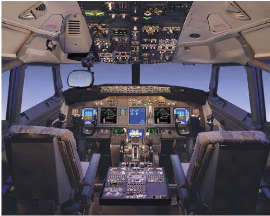
Next-Generation 737s (-600/-700/-800/-900)
Next-Generation 737 Flight Deck
The Next-Generation 737 flight deck is equipped with
industry-leading display and flight management software that promise to reduce
flight delays, and enhance safety and flight crew efficiency. These
technologies include Vertical Situation Display, which shows the current and
predicted flight plath of the airplane and indicates potential conflicts with
terrain, and the Head-Up Display (HUD) which provides pilots with "eye-level"
flight and safety information.
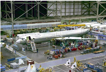
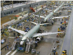
Next-Generation 737s (-600/-700/-800/-900)
Next-Generation 737 Production
Next-Generation 737s line up nose-to-tail on a moving
production line, speeding along at a rate of two inches a minute through the
final assembly process. The moving line, one of several Lean Manufacturing
tactics used at the Renton, Wash., facility, has enhanced quality and reduced
flow time and inventory levels.
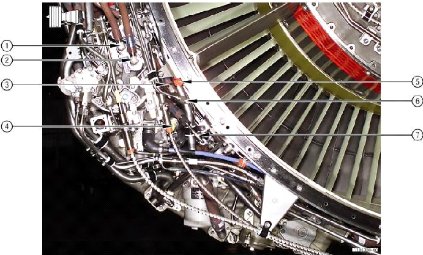
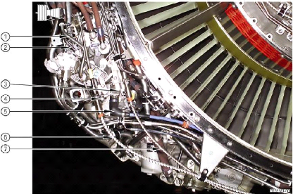
0
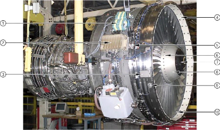
CFM56-3 TRAINING MANUAL
CFM56-3 TRAINING MANUAL
COMPONENT IDENTIFICATION
|
ITEM
NO.
|
IDENTIFY THE
LINE, ACCESSORY OR COMPONENT
|
ITEM
NO.
|
SELECT THE PURPOSE THAT MATCHES
THE LINE ACCESSORY
OR COMPONENT
|
|
8
|
Rear Spinner Cone
|
7
|
Elliptical shape prevents ice formation
|
|
10
|
Abradable Liner
|
6
|
Balance the low pressure system
|
|
9
|
Ps12 Sensing Port {A}
|
3
|
Supplies engine serial number, thrust rating and takeoff
rating
|
|
3
|
Engine Data Plate
|
1
|
Supplies high voltage power to the igniters
|
|
6
|
Balance Screws
|
4
|
Supplies sound suppression
|
|
4
|
Forward Acoustical Panel
|
9I}
|
Prevents direct contact of fan blade into the case during engine
operation
|
|
Ignition Exciter (2)
|
2
|
Electronic over-ride of the MEC
|
|
2
|
Power Management Control (PMC)
|
g
|
Static air pressure from static port to Ps12 manifold
|
|
5
|
T12 Fan Inlet Sensor (stowed)
|
5
|
Fan inlet temperature to PMC
|
|
7
|
Front Spinner Cone
|
8
|
Axial retention of fan blades and provision for balance screw
placement
|
|
|
|
|
|
|
|
|
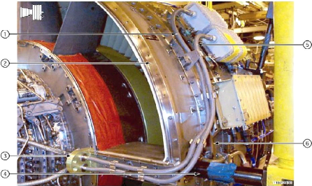
tf CFM56-3 TRAINING MANUAL
COMPONENT IDENTIFICATION
Msrr
|
ITEM
NO.
|
IDENTIFY THE
LINE, ACCESSORY OR COMPONENT
|
ITEM
NO.
|
SELECT THE PURPOSE THAT MATCHES
THE LINE ACCESSORY
OR COMPONENT
|
|
2
|
Fan Frame
|
1
|
Transmits high voltage from the upper exciter to the 6 o'clock
igniter
|
|
1
|
Left Hand Ignition Lead
|
3
|
Supplies cooling air to the right and left ignition lead
conduit for lead coaling
|
|
3
|
Air Manifold
|
6
|
Front section shouldered to give fan blade containment
|
|
6
|
Fan Case
|
2
|
1 of 2 main engine structural frames
|
|
5
|
Right Hand Ignition Lead
|
4
|
Used for engine lifting
|
|
4
|
Front Lifting Trunnion
|
5
|
Transmits high voltage from the lower exciter to tie 4 o'clock
igniter
|
|
|
|
|
|
|
|
|
|
|
|
|
|
|
|
|
|
|
|
|
|
|
|
|
|
|
|
|
|
ITEM NO.
|
IDENTIFY THE
LINE. ACCESSORY CR COMPONENT
|
ITEM
NO.
|
SELECT THE PURPOSE THAT MATCHES
THE LINE ACCESSORY OR
COMPONENT
|
|
7
|
Visual Oil Quantity Window
|
6
|
Supplies oil overflow containment during servicing
|
|
4
|
Oil Tank Anti-Siphon Line
|
4
|
Prevents oil tank siphoning alter engine shutdown
|
|
6
|
Oil Scupper
|
1
|
To support the engine on the ground
|
|
1
|
Fan Frame Ground Handling Mount (Right Hand)
|
2
|
To balance internal sump pressures
|
|
5
|
Gravity Fill Oil Cap
|
7
|
Supplies visual inspection of oil tank service limits
|
|
2sampling Oil Tank Vent Line
|
|
Seals oil tank and allows for servicing and oil
|
|
3
|
Oil Tank Quantity Transmitter
|
3
|
Transmit oil tank quantity to flight deck
|
|
|
|
|
|
|
|
|
|
|
|
|
|
|
|
|
|
|
|
|
|
ITEM NO.
|
IDENTIFY THE
LINE, ACCESSORY OR COMPONENT
|
ITEM
NO.
|
SELECT THE PURPOSE THAT MATCHES
THE LINE ACCESSORY
OR COMPONENT
|
|
3
|
Oil Tank Pressure Fill and Overflow Ports
|
1
|
Supplies Ni speed signal to PMC and flight deck
|
|
2
|
Oil Scavenge Return Line
|
4
|
Supplies oil from ail tank to lube unit pressure pump
|
|
5
|
Oil Tank
|
5
|
Storage of engine lubrication oil
|
|
4
|
Lube Unit Supply Line
|
2
|
Supplies scavenge oil return from servo heater to oil tank
|
|
1
|
N1 Speed Sensor
|
3
|
Supplies remote pressure servicing of the oil tank
|
|
|
|
|
|
|
|
|
|
|
|
|
|
|
|
|
|
|
|
|
|
|
|
|
|
|
|
|
|
ITEM NO.
|
IDENTIFY THE
LINE, ACCESSORY CR COMPONENT
|
ITEM
NO.
|
SELECT THE PURPOSE THAT MATCHES
THE LINE ACCESSORY OR
COMPONENT
|
|
4
|
An Acoustical Panel
|
5
|
Cooling of CSD/IDG oil
|
|
2
|
Mid Acoustical Panel
|
2
|
Sound Suppression
|
|
5
|
CSDIIDG Oil Cooler Pad
|
3
|
Air directed to the aircraft generator for cooling
|
|
3
|
Generator Cooling Inlet
|
4
|
Sound suppression
|
|
t
|
Outlet Guide Vanes (80)
|
1
|
Points tan discharge air flow in a straight path
|
|
|
|
|
|
|
|
|
|
|
|
|
|
|
|
|
|
|
|
|
|
|
|
|
|
|
|
|
|
ITEM NO.
|
IDENTIFY THE
LINE, ACCESSORY OR COMPONENT
|
ITEM
NO.
|
SELECT THE PURPOSE THAT MATCHES
THE LINE ACCESSORY
OR COMPONENT
|
|
6
|
Alternate Vibration Sensor Pad
|
F
|
Supplies HPC bleed air to the HPT shroud to increase engine
efficiency
|
|
8
|
T2.5 (UT) Sensor (Inside Frame)
|
8
|
Supplies compressor inlet temperature to MEC
|
|
5
|
Air Ignition Tube
|
2
|
Supplies static rigging of variable stator vane actuator to the
system
|
|
High Pressure Turbine Clearance Control Valve7 (HPTCCV)
|
1
|
Ignite fuel/air mixture and BSI port 516
|
|
2
|
VSV Actuator Rig Pin Hole (Right Side)
|
4
|
Connects No. 1 bearing vibration sensor with aircraft
|
|
4
|
Electrical Connector, Bearing Vibration Sensor
|
3
|
To connect each VSV actuation ring
|
|
1
|
Igniter - Lower Right Hand Side Combustor Case
|
8
|
Alternate No_ 1 bearing vibration sensor mounting pad
|
|
3
|
VSV Actuation Connecting Links
|
5
|
Supplies cooling air from the booster to the air manifold
|
|
|
|
|
|
|
|
|
|
|
|
|
|
|
|
|
|
ITEM NO.
|
IDENTIFY THE
LINE, ACCESSORY OR COMPONENT
|
ITEM
NO.
|
SELECT THE PURPOSE THAT MATCHES
THE LINE ACCESSORY
OR COMPONENT
|
|
2
|
Bore scope Port S7
|
3
|
BS/ stage 8 trailing edge and stage 9 leading edge HPC
|
|
3
|
Borescope Port S9
|
1
|
BSI stage 5 trailing edge and stage 6 leading edge HPC
|
|
Bores-cope Port S6
|
2
|
BSI stage 6 trailing edge and stage 7 leading edge HPC
|
|
6
|
Borescope Port S3
|
6
|
BSI stage 1 trailing edge and stage 2 leading edge HPC
|
|
7
|
Borescope Port S1
|
7
|
BS/ !CV and leading edge stage 1 HPC
|
|
5
|
Borescope Port S5
|
8
|
BSI stage 2 trailing edge and stage 3 leading edge HPC
|
|
6
|
Borescope Port S2
|
5
|
BSI stage 4 trailing edge and stage 5 leading edge HPC
|
|
g
|
Borescope Port S4
|
9
|
BSI stage 3 trailing edge and stage 4 leading edge HPC
|
|
4
|
Bore scope Port 58
|
4
|
BSI stage 7 trailing edge and stage 8 leading edge HPC
|
|
|
|
|
|
|
|
|
|
|
|
|
|
ITEM NO.
|
IDENTIFY THE
LINE, ACCESSORY CR COMPONENT
|
ITEM
NO.
|
SELECT THE PURPOSE THAT MATCHES
THE LINE ACCESSORY
OR COMPONENT
|
|
2
|
IGV Actuation Half Ring
|
5
|
Stage 2 VSV scheduling
|
|
1
|
Stage 3 Actuation Half Ring
|
4
|
Connects turbine frame bearing vibration sensor to aircraft
|
|
5
|
Stage 2 Actuation Half Ring
|
2
|
IGV angle scheduling
|
|
3
|
Stage 1 Actuation Half Ring
|
1
|
Stage 3 VSV scheduling
|
|
4
|
Electric Connector, Bearing Vibration Sensor
|
3
|
Stage t VSV scheduling
|
|
|
|
|
|
|
|
|
|
|
|
|
|
|
|
|
|
|
|
|
|
|
|
|
|
|
|
|
|
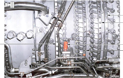
ITEM NO.
|
IDENTIFY THE
LINE, ACCESSORY OR COMPONENT
|
ITEM
NO.
|
SELECT THE PURPOSE THAT MATCHES
THE LINE ACCESSORY OR
COMPONENT
|
|
1
|
Fuel Nozzle (20}
|
1
|
Supplies fuel to the combustion chamber
|
|
2
|
Shrouded Fuel Manifold
|
4
|
Supplies stage 9 bleed air to the HPTCCV
|
|
4
|
HPC Stage 9 Bleed Tap
|
2
|
Supplies fuel to the fuel nozzles
|
|
5
|
Bleed Bias Sensor (C BP)
|
5
|
Senses use of customer bleed air
|
|
g
|
HPTCCV Discharge Manifold
|
3
|
Supplies stage 5, stage 9, or mixed bleed air to HPT shroud
|
|
|
|
|
|
|
|
|
|
|
|
|
|
|
|
|
|
|
|
|
|
|
|
|
|
|
|
|
|
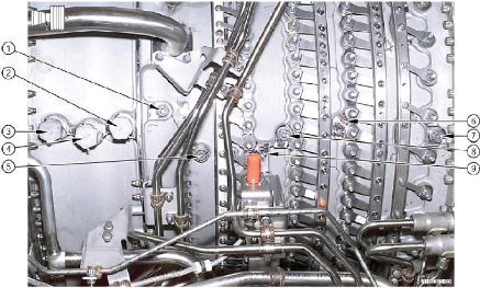
ITEM NO.
|
IDENTIFY THE
LINE, ACCESSORY OR COMPONENT
|
ITEM
NO.
|
SELECT THE PURPOSE THAT MATCHES
THE LINE ACCESSORY OR
COMPONENT
|
|
3
|
Turbine Frame
|
5
|
Supplies fan discharge air to LPT Case for cooling
|
|
7
|
Distribution Box LPT Case Gaoling
|
2
|
Prevents flame propagation in the center vent tube
|
|
5
|
LPT Case Cooling Manifold
|
1
|
Supports the engine on the ground
|
|
1
|
Turbine Frame Ground Handling Mount
|
|
Supplies fan discharge air to LPT case cooling manifold
|
|
2
|
Flame Arrestor
|
4
|
Connects EGT system to flight deck indicator
|
|
4
|
T4.95 (EGT) Junction Connector
|
3
|
Second structure frame of engine
|
|
6
|
T4.95 (EGT) Thermocouple Probes (9)
|
6
|
Sense exhaust gas temperature
|
|
|
|
|
|
|
|
|
|
|
|
|
|
|
|
|
|
|
|
|
|
ITEM NC.
|
IDENTIFY THE
LINE, ACCESSORY OR COMPONENT
|
ITEM
NO.
|
SELECT THE PURPOSE THAT MATCHES
THE LINE ACCESSORY OR
COMPONENT
|
|
I
|
Borescope Port S22
|
2
|
Scavenge return of oil from aft surnp to Tube unit
|
|
2
|
Aft Sump Oil Scavenge Line
|
|
BSI stage 3 leading edge and stage 2 trailing edge LPTR
|
|
5
|
Borescope Port 517
|
3
|
Supplies oil to aft sump frarri lube unit
|
|
3
|
Aft Sump Supply Line
|
|
BSI HPTR trailing edge and stage 1 LPTR leading edge
|
|
4
|
Borescope Port 521
|
I
|
BSI stage 4 leading edge and stage 3 trailing edge LPTR
|
|
|
|
|
|
|
|
|
|
|
|
|
|
|
|
|
|
|
|
|
|
|
|
|
|
|
|
|
|
ITEM NO.
|
IDENTIFY THE
LINE, ACCESSORY CR COMPONENT
|
ITEM
NO.
|
SELECT THE PURPOSE THAT MATCHES
THE LINE ACCESSORY OR
COMPONENT
|
|
4
|
Low Pressure Turbine Stator Case
|
3
|
Supplies stage 5, stage 9, and mixed bleed air to the HPT
shroud
|
|
2
|
HPC Stage 9 Bleed Port (4)
|
8
|
Support the HPT shrouds in the HPTR area
|
|
9
|
HPC Stage 5 Bleed Manifold (4) LPT Stage 1 Coaling
|
2
|
Stage 9 customer bleed air
|
|
8
|
HPT Shroud Support
|
1
|
Supplies fuel to left hand side no77ies
|
|
1
|
Fuel Manifold (Left Hand Side)
|
5
|
Connect EGT system to flight deck indicator
|
|
5
|
T4.95 (EGT) Junction Connector
|
|
Transmits vibration signal from the turbine frame sensor to
connector
|
|
7
|
Turbine Frame Vibration Sensor Cable
|
4
|
Enclose the four LPT stages
|
|
3
|
HPTCCV Discharge Manifold
|
|
Supplies stage 5 bleed air for stage T LPT nozzle cooling
|
|
6
|
Barescope Port 518
|
8
|
BSI HPTR trailing edge and stage 1 HPTR leading
|
|
|
|
|
|
|
|
|
|
|
|
|
|
ITEM NO.
|
IDENTIFY THE
LINE, ACCESSORY CR COMPONENT
|
ITEM
NO.
|
SELECT THE PURPOSE THAT MATCHES
THE LINE ACCESSORY OR
COMPONENT
|
|
3
|
Lett Hand Ignition Lead
|
5
|
Stage 5 customer bleed air
|
|
1
|
HPC Stage 5 Start Bleed Valve
|
8
|
Supplies fuel to the combustion chamber
|
|
6
|
Igniter--Lower Left Hand Side Combustion Case
|
3
|
Transmits high voltage from the upper exciter to the 8:00
igniter
|
|
a
|
Fuel Nozzle (20)
|
2
|
Supplies start air pressure to the HPC stage 5 start bleed
valve
|
|
4
|
CDP (1333) Tap and Signal Line
|
6
|
Ignites the fuel/air mixture and 531 Port 511
|
|
5
|
HPC Stage Bleed Port (3)
|
1
|
Aerodynamically unloads the HPC during start
|
|
7
|
combustion Case
|
4
|
Transmits the compressor discharge pressure signal to the MEC
|
|
2
|
Air Signal Start Bleed Tube
|
7
|
Contains the combustion chamber
|
|
|
|
|
|
|
|
|
|
|
|
|
|
|
|
|
|
ITEM NO.
|
IDENTIFY THE
LINE, ACCESSORY OR COMPONENT
|
ITEM
NO.
|
SELECT THE PURPOSE THAT MATCHES
THE LINE ACCESSORY OR
COMPONENT
|
|
-1Master
V BV Bal! Screw Actuator { 1 l
|
q
|
Changes the VBV fuel gear motion into VBV linear rotational
motion
|
|
3
|
Fan Duct Pane!
|
2
|
Supplies by-pass of primary airflow into the secondary airflow
|
|
2
|
Variable Bleed Valve (12)
|
3
|
Points airflow from the booster through the open VBV doors to the
fan by-pass air
|
|
6
|
VBV Stop Mechanism
|
6
|
Controls the range of movement of the VBV fuel gear motor
|
|
4
|
Kicker Stop
|
5
|
Transmits VBV master ball screw position to feedback cable
|
|
5
|
Feedback Rod Clevis
|
4
|
Supplies a stop for the free lever
|
|
|
|
|
|
|
|
|
|
|
|
|
|
|
|
|
|
|
|
|
|
|
|
|
|
ITEM NO.
|
IDENTIFY THE
LINE, ACCESSORY OR COMPONENT
|
ITEM
NO.
|
SELECT THE PURPOSE THAT MATCHES
THE LINE ACCESSORY
OR COMPONENT
|
|
4
|
Return Lever
|
1
|
Uses fuel pressure to turn the motor drive, which opens or closes
the VBVs
|
|
2
|
VBV Feedback Cable Rod End Bearing
|
3
|
Supplies a biased feedback signal to the MEC to further open VBV
doors
|
|
3
|
Free Lever
|
|
Transmits rod end fuel pressure from the MEC to the VSV
actuator
|
|
6
|
VSV Rod End Pressure Line
|
5
|
Transmits head end fuel pressure from the MEC to the VSV
actuator
|
|
5
|
VSV Head End Pressure Line
|
2
|
Adjusts the length or the VBV feedback cable during the travel
check
|
|
1
|
VBV Gear Motor
|
4
|
Returns the VBV to the normal MEC schedule
|
|
|
|
|
|
|
|
|
|
|
|
|
|
|
|
|
|
|
|
|
|
|
|
|
|
ITEM NO.
|
IDENTIFY THE
LINE, ACCESSORY OR COMPONENT
|
ITEM
NO.
|
SELECT THE PURPOSE THAT MATCHES
THE LINE ACCESSORY
OR COMPONENT
|
|
6
|
T Signal Line
|
6
|
Carmes Pb or Pcü fuel pressure from the MEC to
the HPTCCV 9 stage valve
|
|
4
|
Idle Solenoid
|
-.
|
Carries Pb or Pc fuel pressure from the MEC to the HPTCCV
5i stage valve
|
|
3
|
TC3 Signal Line (-3132/-3C only]
|
5
|
Drains oil from the forward sump seal cavity to overboard
|
|
5
|
Cavity Drain
|
2
|
Carries fuel pressure from the MEC to the VSV actuators to
open the VSVs
|
|
2
|
VSV Rad End Pressure Line
|
4
|
Electrically supplies flight and ground idle (high and low
idle) by the aircraft's flight condition
|
|
9
|
VSV Head End Pressure tine
|
1
|
Carries fuel pressure from the MEC to the VSV actuators to
close the VSVs
|
|
7
|
TG1 Signal Line
|
|
Signal pressure to the timer solenoid during a takeoff with n2
larger than 95%
|
|
|
|
|
|
|
|
|
|
|
|
|
|
|
|
|
|
|
|
|
|
ITEM NO.
|
IDENTIFY THE
LINE, ACCESSORY OR COMPONENT
|
ITEM
NO.
|
SELECT THE PURPOSE THAT MATCHES
THE LINE ACCESSORY
OR COMPONENT
|
|
5
|
Electric Connector
|
5
|
Transmits PLA from the MEC to the PMC and transmits the TMC from
the PMC to the MEC
|
|
6
|
VSV Feedback Cable
|
4
|
To rig the position of the pointer with the VSV ng notch
|
|
1
|
Pb Pressure Line
|
|
To rig the position of the pointer with the VBV rig notch
|
|
7
|
VBV Feedback Cable
|
|
1sensor
Cames Pb (low) pressure from the CIT (T25) to the MEC
|
|
4
|
Adjustment Screw VSV Feedback Cable
|
2
|
Carries P6 (high) pressure from the MEC to the CIT (T25)
sensor
|
|
2
|
P6 Pressure Line
|
7
|
Indicates VBV door position to the MEC
|
|
3
|
Adjustment Screw VBV Feedback Cable
|
6
|
Indicates VSV position to the MEC
|
|
|
|
|
|
|
|
|
|
|
|
|
|
|
|
|
|
|
|
|
|
ITEM NO.
|
IDENTIFY THE
LINE, ACCESSORY OR COMPONENT
|
ITEM
NO.
|
SELECT THE PURPOSE THAT MATCHES
THE LINE ACCESSORY
OR COMPONENT
|
|
10
|
Oil Scavenge Return Line
|
12
|
Transmits flight deck throttle demand to the MEC
|
|
4
|
Oil Scavenge Line
|
8
|
Supplies static rigging procedure of the VSV actuator ta the
system
|
|
8
|
VSV Actuator Rig Pin Hole (Left Side)
|
11
|
Supplies positive fuel ON/OFF selection
|
|
g
|
VSV Actuator (Left Side)
|
1
|
Supplies fuel from the servo fuel heater to the MEC
|
|
3
|
VBV Open Part Line
|
|
Fuel pressure from the MEC to the rod end or the head end
actuates the VSV system
|
|
12Power
Lever
|
10
|
Supplies scavenge oil return from the servo heater to the oil
tank
|
|
11
|
Fuel Shutoff Lever
|
7
|
Holds all servo mechanism lines
|
|
5
|
Full Reverse Power Lever Stop
|
6
|
Supplies stoppage for the power lever at its
130-degree stop (non-adjustable)
|
|
-1
|
Fuel Supply Line
|
5
|
Supplies mechanical stoppage for the power lever
(non-adjustable)
|
|
7
|
9 O'clock Tube bundle
|
|
Supplies oil from the scavenge tiller to the servo Mel heat
exchanger
|
|
2
|
VBV Close Port Line
|
3
|
Supplies fuel from the MEC ta the VBV motor to open the
VBVs
|
|
6
|
Full Forward Power Lever Stop
|
2
|
Supplies fuel from the MEC to the VBV motor to close the
VBVs
|
|
cp
|
|
|
|
|
|
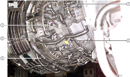
ITEM NO.
|
IDENTIFY THE
LINE, ACCESSORY OR COMPONENT
|
ITEM
NO.
|
SELECT THE PURPOSE THAT MATCHES
THE LINE ACCESSORY
OR COMPONENT
|
|
6
|
LP Fuel Pump Screen Assembly
|
tp
|
De-ices the servo fuel by convection transfer of heal from the
scavenge ail
|
|
1D
|
Servo Fuel Heater
|
8
|
Transmits power from the 1GB to the AGB for the accessories
|
|
8
|
Transfer Gearbox
|
3
|
Supplies gear drive for the accessories
|
|
4
|
Main Fuel/Oil Heat Exchanger
|
6
|
Gives access to the LP stage impeller for verification of
rotation
|
|
9
|
Fuel Supply Heater Tube
|
t
|
Supplies vent air from AGB ta the forward sump. & protects
horizontal drive shaft
|
|
6
|
Pb Pressure Line {-3B21-3C only}
|
9
|
Transmits fuel from the pump to the servo healer
|
|
7
|
Fuel Pump
|
|
Two-stage pump that supplies fuel pressure and drive far the
MEC
|
|
2
|
Fuel Supply Line
|
5
|
Pb supply to the timer and timer solenoid valve from the fuel
pump
|
|
1
|
Horizontal Drive Shaft Housing
|
2
|
Transmits fuel from the MEC to the fuel flow meter
|
|
g
|
Accessory Gearbox
|
4
|
Cools the engine oil through convection transfer of heat from
the oil to the fuel
|
|
17
|
Main Engine Control (MEC)
|
7 7
|
Supplies schedule fuel for combustion and servo operation
|
|
|
|
|
|
ITEM NO.
|
IDENTIFY THE
LINE, ACCESSORY OR COMPONENT
|
ITEM
NO.
|
SELECT THE PURPOSE THAT MATCHES
THE LINE ACCESSORY OR
COMPONENT
|
|
6
|
Forward Sump MCD
|
g
|
Collects and filters metallic and non-metallic particles from the
AGBITGB sumps
|
|
2
|
Lube Supply Filter
|
|
Supplies one supply pump and three scavenge pumps for oil
circulation
|
|
3
|
PS12 Signal Line
|
|
Supplies scavenge oil from the lube unit to the scavenge
filter element
|
|
4
|
Oil Scavenge Line
|
|
Collects and fillers metallic and non-metallic particles from the
all sump
|
|
5
|
Lubrication Unit
|
3
|
Supplies static air pressure from the PS-12 manifold
to the MEC
|
|
g
|
AGB/TGB Sump MCD
|
t
|
Filters the fuel before the fuel flows to the high pressure
stage of the fuel pump
|
|
7
|
All Sump MCD
|
2
|
Filters the supply oil before the oil flows to the sumps
|
|
f
|
Fuel Filter
|
|
Collects and filters metallic and non-metallic particles from the
forward sump
|
|
|
|
|
|
|
|
|
|
|
|
|
|
|
|
|
|
ITEM NO.
|
IDENTIFY THE
LINE, ACCESSORY OR COMPONENT
|
ITEM
NO.
|
SELECT THE PURPOSE THAT MATCHES
THE LINE ACCESSORY
OR COMPONENT
|
|
5
|
AGB Drain Port
|
4
|
Supplies oil from the lube unit to the AGB
|
|
2
|
Lute Scavenge Filter
|
2
|
Filters the scavenge oil before the oil flows to the servo
heater
|
|
1
|
AGB Alignment Turnbuckle
|
5
|
Supplies drainage of the AGB sump
|
|
7
|
MCD Retention Bar
|
T
|
Supplies a positive lock of the MCD, and prevents partial
disengagement
|
|
4
|
Oil Supply Line
|
6
|
Connects the TGB to the AGB to supply oil scavenging
|
|
.3
|
Visual Gagging Indicator
|
1
|
Aligns the AGB for honzontal drive shaft installation
|
|
6
|
Oil Scavenge Line
|
3
|
Supplies a visual indication of the lube supply titter dogging
|
|
|
|
|
|
|
|
|
|
|
|
|
|
|
|
|
|
|
|
|
|
ITEM NO.
|
IDENTIFY THE
LINE, ACCESSORY OR COMPONENT
|
ITEM
NO.
|
SELECT THE PURPOSE THAT MATCHES
THE LINE ACCESSORY
OR COMPONENT
|
|
7
|
TS5 Pressure Line (-3B21-3C only)
|
3
|
Changes the operation of the HPTCCV during takeoff
|
|
1
|
P7 Pressure Line
|
2
|
Transmits Pb (low) pressure from the T2 sensor to the MEC
|
|
3
|
HPTCCV Timer (3B21 3C only)
|
7
|
Supplies output of Pc or Pb from the TCC timer to the TCC
valve to control stage 5 bleed*
|
|
4
|
HPTCCV Timer Lockout Solenoid (-3C only)
|
|
Supplies output of Pc or Pb from the TCC timer to the TCC
valve to control stage 9 bleed**
|
|
2
|
Pb Pressure Line
|
5
|
Controls the operation of the stage 5 valve of the TCCV (timer
disarmed)
|
|
5
|
TC1 Pressure Line (-3B2/ C only)
|
|
Weight-on-wheels sensing relay, airborne condition prevents TC3
fuel flaw to TCCV tinier
|
|
g
|
TS9 Pressure Line (-3B2f-3C only)
|
1
|
Transmits P7 (high) pressure from the MEC to the T2 sensor
|
|
|
|
|
|
|
|
*NOTE: Timer disarmed TS5 ports Tci fuel
pressure_
|
|
|
|
|
|
|
|
**NOTE: Timer disarmed TS9 ports Tc2 fuel pressure.
|
|
|
|
|
|
ITEM NO.
|
IDENTIFY THE
LINE, ACCESSORY OR COMPONENT
|
ITEM
NO.
|
SELECT THE PURPOSE THAT MATCHES
THE LINE ACCESSORY
OR COMPONENT
|
|
1
|
BellowsNalve Housing (T2)
|
6
|
Pc pressure holds the timer latching valve in the latched
position
|
|
7
|
Pb Pressure Line (-3b2f-3C only)
|
3
|
Controls the operation of the stage 9 valve of the TCCV (timer
disarmed)
|
|
4
|
only) hP~ CV Timer Adjustment Screw (-3132/-3C
|
7
|
Supplies low pressure for timer operation
|
|
6
|
Pc Pressure Line {621-3G only)
|
1
|
Changes the fuel pressure to the MEC with changes in inlet
temperature
|
|
3
|
T Pressure Line (-3621G only)
|
5
|
The timer starts its sequence when pressure indicates to
lock-out solenoid that N2 is 95%
|
|
2
|
T2 Sensor (Stowed)
|
|
Supplies the adjustment for the timer operation speed
|
|
5
|
TC3 Pressure Line {-3B2)-3C only)
|
2
|
Supplies the fan inlet temperature to the MEC
|
|
|
|
|
|
|
|
*NOTE: This lets the timer open one time each
engine cycle
|
|
|
|
|
|
|
|
|
|
|
|
|
|
ITEM NO.
|
IDENTIFY THE
LINE, ACCESSORY OR COMPONENT
|
ITEM
NO.
|
SELECT THE PURPOSE THAT MATCHES
THE LINE ACCESSORY
OR COMPONENT
|
|
4
|
Hand Cranking Pad
|
2
|
Drains to Overboard
|
|
2
|
Hydraulic Ptimp Pad Drain
|
1
|
Supports the hydraulic pump
|
|
1
|
Hydraulic Pump Pad
|
G
|
Drains to overboard
|
|
,
|
Starter and Nand Cranking Pad Drain
|
g
|
Drains to overboard
|
|
9
|
CSDIIDG Cavity Reservoir Standpipe Drain
|
5
|
Supports the air starter
|
|
5
|
Pneumatic Starter Pad
|
4
|
Lets the operator rotate the core during maintenance
|
|
7
|
CSDiIDG Pad
|
3
|
Transmits power to the PMC and flight deck N2 speed
indication
|
|
8
|
CSDJIDG Pad Drain
|
7
|
Supports the CSDfIDG
|
|
3
|
Contra) Alternator
|
|
Makes sure oil level of the CSDiIDG is normal during servicing
|
|
|
|
|
|
|
|
|
|
|
|
|
|
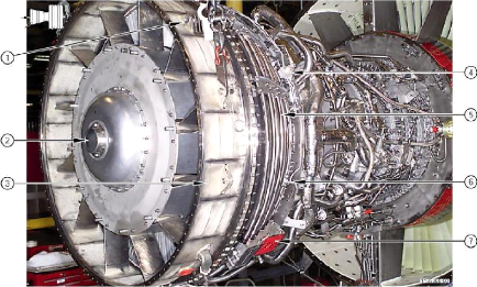
ITEM NO.
|
IDENTIFY THE
LINE, ACCESSORY OR
COMPONENT
|
ITEM
NO.
|
SELECT THE PURPOSE THAT MATCHES
THE LINE ACCESSORY
OR COMPONENT
|
|
2
|
Core Major Module
|
1
|
Contains the LPT rotor, LPT stator, LPT shaft,
and the LPT frame
|
|
3
|
Fan Major Module
|
3
|
Contains tanibooster, No. 1 and 2 bearing
support, IGB, No_ 3 bearing, fan frame, TGB and AGB
|
|
Low Pressure Turbine (LPT) Major Module
|
2
|
Contains HPC rotor & stators, combustor case & liner,
HPT nomme & rotor, and LPT nozzle
|
|
|
|
|
|
|
|
|
|
|
|
|
|
|
|
|
|
|
|
|
|
|
|
|
|
|
|
|
|
|
|
|
|
|
|
|
| 
