|
i
Dedication
To the God Almighty father
To my dad
To my dearest
mom
To my beloved sisters and brothers
To my classmates, friends and
relatives
I dedicate this final reeasearch.
HUNDWITIRO Herménégilde
ii
Declaration
I, HUNDWITIRO Herménégilde, hereby declare that
this dissertation entitled «The implementation of web based system
for the improvement of good governance in the development of Rwandan
Districts» is my own work and has not been submitted anywhere for
award of any degree.
HUNDWITIRO Herménégilde
Signature
iii
Acknowledgement
The District Invitation to Tender Management Information
System (DITMIS) is a research, which was initiated as a final project to submit
in the fulfillment of the requirements of the award of Bachelor's Degree in
Information Technology Application in Management.
This work has been a result of joint effort from different
persons, without whom the completion of this research would not be success.
This is the time for me to acknowledge their incomparable help.
First of all, I thank the almighty God who always guide and
protect me and make possible what seems to be impossible in my life.
My sincere thanks to Mr. KAGARAMA John Baptista my supervisor for
his endless guidance and supervision in the achievement of this work.
A heartfelt to my parents Mr. NZABAHIMANA Jean Bosco and Mrs.
MUKAMASABO Béatrice, for their great commitment and invaluable moral and
material support, will always be remembered, to my beloved Teachers for their
education with endless love and support during my studies.
I wish to extend my deep gratitude to my friends TWAHIRWA Jean
Baptiste, KABERA Lambert and HAKIZIMANA Jean Claude for their help, advices,
cooperation and encouragement, my sincere gratitude as well.
I am also grateful to my brothers, sisters, relatives and
classmates for the cooperation and encouragement, my sincere gratitude as
well.
The particular thanks to the Department of Management, the
faculty of Economics and Management, the National University of Rwanda and the
Rwandan Government. Their support made working on this project possible.
iv
Table of contents
DEDICATION I
DECLARATION II
ACKNOWLEDGEMENT III
TABLE OF CONTENTS IV
LIST OF ACRONYMS AND ABBREVIATIONS VI
LIST OF TABLES VIII
LIST OF FIGURES IX
ABSTRACT X
CHAPTER1. GENERAL INTRODUCTION 1
1.1. INTRODUCTION 1
1.2. THE PROBLEM STATEMENT 1
1.3. OBJECTIVES OF THE STUDY 2
General Objective 2
Specific Objective 2
1.4. MOTIVATION AND INTEREST OF THE PROJECT 3
1.5. THE PROJECT QUESTIONS 3
1.6. THE PROJECT HYPOTHESES 4
1.7. SCOPE OF THE PROJECT 4
1.8. METHODOLOGY 4
1.9. ORGANIZATION OF THE PROJECT 5
CHAPTER. 2. THEORETICAL CONCEPTS AND DEFINITIONS
6
2.1. INTRODUCTION 6
2.2. INFORMATION SYSTEM 6
2.2.1. DEFINITION 6
2.3. DATABASE CONCEPTS 8
2.3.1. Definition and terminology 8
2.3.2. Database design principles 10
2.3.3 Normalization 11
2.3.4. Database management system 12
2.3.5. Data processing architecture 13
2.4. WEB- BASED TECHNOLOGIES CONCEPTS 13
2.4.1. Computer network 13
2.4.2. Internet and World Wide Web 17
V
3.1 INTRODUCTION 19
3.2. SOFTWARE ENGINEERING APPROACH 19
3.2.1. Software life cycle 19
3.2.2. The waterfall model 20
CHAPTER IV. DEVELOPMENT AND IMPLEMENTATION OF THE WEB
BASED SYSTEM. 24
4.1. INTRODUCTION 24
4.2. GENERAL DESCRIPTION OF NYAMAGABE DISTRICT 24
4.3. SOFTWARE DEVELOPMENT 24
4.3.1 Analysis of the existing Information System 24
4.3.2. The proposed system. 25
4.3.3. System Requirement Specification 25
4.3.4. General Description of DITMIS 25
4.3.5. Specific Requirements 26
4.3.6. Process Modeling 28
4.3.7 Tools Used 35
4.3.8 Data Dictionary 37
4.3.9 Implementation 41
CHAPTER 5: CONCLUSION AND RECOMMENDATIONS 49
5.1 CONCLUSION 49
5.2 RECOMMENDATIONS 50
5.3 FUTURE WORK 50
BIBLIOGRAPHY 51
A) BOOKS: 51
B) WEB REFERENCES: 51
vi
List of Acronyms and Abbreviations
1.BITAM : Bachelor of Information Technology
Application in Management 2.BCFN:Boyce Codd Normal Form
3.CPU:Central Processing Unit
4.CAN:Campus Area Network
5.CSS:Cascading Style Sheets
6. DB: Database
7.DBMS:Database Management System
8.DFM:Data FlowModel
9.DFD:Data Flow Diagram
10.DITMIS:District Invitation to Tender
Management Information System 11.DKNF: Domain Key normal
form
12.DPP:Desktop Publishing Program
13.ECMA:Europian Computer Manufacturers
Association
14.ERD:Entity Relationship Diagram 15.G
C : Government Citizen
16.HTML:Hyper Text Mark_up Language
17.HTTP:Hyper Text Transfer Protocol
18.ICT: Information Technology and Technology
19.I S: Information System
20.IT :Information Technology
21.ITAA: Information Technology Association of
America
22.IP:Internet Protocol
23.LAN:Local Area Network
24.MAN:Metropolitan Area Network
25.MIS:Management Information System 26.N F:
Normal Form
27.PAN:Personnal Area Network
vii
28.PC: Personnal Computer
29.PHP:Hypertext Preprocessor
30.RDBMS:Relational Database Management System
31.SAN:Storage Area Network
32.SVG: Scalable Vector Graphics
33.TCI IP: Transmission Control Protocol
Internet Protocol 34.VPN:Virtual Private Network
35.WAN:Wide Area Network
36.WEBAPP:Web application
37.WWW:World Wide Web
38.XHTML:Extensible Hyper Text Markup Language
39.XML:Extensible Hyper Text Markup Language
viii
List of Tables
TABLE 4 .1: ACTOR GOAL LIST 26
TABLE: 4.2 .DITMIS _ LIST OF TABLES 33
TABLE 4.3. APPLICANT TABLE 38
TABLE 4.4 ANNOUNCEMENT 38
TABLE 4.5: CHAT 38
TABLE 4.6 : COMMENT 39
TABLE 4.7: PASSWORD 39
TABLE 4.8: RESULTS 40
TABLE 4.9 ATTACHFILE 40
TABLE 4.10: SCREEN GLOSSARY 42
ix
List of Figures
FIGURE 3.1: THE CLASSICAL SEQUENTIAL SOFTWARE LIFE-CYCLE MODEL
20
FIGURE 3.2. THE WATERFALL MODEL 21
FIGURE 4.1: SYSTEM OUTLINE FOR DITMIS 29
FIGURE 4. 2: DISTRICT INVITATION TO TENDER MANAGEMENT
INFORMATION SYSTEM CONTEXT DIAGRAM / LEVEL 0 31
FIGURE4.3 LEVEL1 DATA FLOW DIAGRAM 32
FIGURE 4.4 E R DIAGRAM 34
TABLE 4.4 ANNOUNCEMENT 38
FIGURE 4.5: THE MAIN PAGE 43
FIGURE 4.6: ANNOUNCEMENT PAGE 43
FIGURE 4.7: END OF ANNOUNCEMENT PAGE 44
FIGURE 4.8: THE TENDER PAGE 44
FIGURE 4.9: THE DETAILS FOR TENDER PAGE 45
FIGURE 4.10: THE APPLICANT PAGE 45
FIGURE 4.11: THE PAGE FOR UPLOADING OTHER FILES. 46
FIGURE 4.12: THE ADMINISTRATOR PAGE. 46
FIGURE 4.13: THE VIEW ALL APPLICANTS PAGE 47
FIGURE 4.14: THE PAGE FOR ALL FILES UPLOADED. 47
FIGURE 4.15: THE PAGE FOR SUBMITTING A COMMENT. 48
FIGURE 4.16: THE PAGE FOR PRINTING AN ANNOUNCEMENT. 48
x
Abstract
The growth and development of information and technologies
(ICT's) has led to their wide diffusion and application, thus increasing their
economic and social impact. The internet undertakes a wide range of activities
aimed at improving our understanding of how ICTs contribute to sustainable
economic growth and social well being and their role in the shift toward
knowledge based societies.
Trust among the users of ICT networks is increasing priority
for business, industry and governments. Information and Communication and
Technologies (ICTs) can help meet development objectives, in particular
international development goals for poverty reduction, education, health and
environment.
This research is conceived with the aim of providing an
adequate solution that will help citizens to get information about the tenders
available in the Districts, the details about those tenders and have the
possibility to apply for any tender. The DITMIS uses the advantages of
Information and Communication Technologies (ICTs) as mentioned above.
The objective of this study is to provide a web based
application able to assist anyone to get information about the tenders
available in the Districts, able to read the announcement for an tender and
have the opportunity for the application. The web based application to develop
will have a web interface where applicants can read the announcement for
tender, the details about the tenders and make the application via internet.
To achieve the fixed objectives, we have used the waterfall
model as a software development process model to develop the web based
application. Interviews and documentation also are used as the major data
collection techniques.
By the end of this document, interfaces for users are designed
with PHP, and listed in the interfaces
Glossary subsection. Finally, conclusion and recommendations are
made to facilitate the usage and further improvement of this application.
CHAPTER1. GENERAL INTRODUCTION
1.1. Introduction
The Information and Communication Technologies (ICT) are being
increasingly used by the governments to deliver its services at the locations
convenient to the citizens. The web based system attempt to offer the services
of central agencies (like district administration, cooperative union, and state
and central government departments) to the citizens at their village door
steps.
Information Technologies is widely used and rapidly becoming a
common asset of modern socio-economic life in this new world of globalization
.These technologies are opening opportunities and new avenues for all.
Our country Rwanda has a long way to reach to successful in
this area .Software development and the use of automated systems, network
systems development and the needs to share information within the country and
with outside world , is what among other things that hold largely the degree of
measure of development in the Rwandan society.
These applications utilize the ICT in offering improved and
affordable connectivity and processing solutions. Several Government-Citizen
(G-C) e-Governments have attempted to adopt these technologies to improve the
reach, enhance the base, minimize the processing costs, increase transparency,
and reduce the cycle times.
A large number of web based system, aimed at offering easy
access to citizen service and improved processing of government-to-citizen
transactions. Some of these have drawn international attention and have won
prestigious awards for their innovative approaches.
1.2. The problem statement
In Rwandan districts like other central departments in the
country, the improvement of good-governance is a key feature for the
development of the country.
Besides, Rwandan districts have recognized a big problem of
lacking the system which may help the easy processing of the daily activities
in order to easily achieve the delivery of better services to their people.
For instance using this system will help citizens to know the
information about the tenders available in the district and they will have the
possibility to apply for any tender on line. They will be able to give their
comments on tenders' process in order to increase the transparency and the
accountability for the invitation to tender process.
The existing tender system at Nyamagabe District is paper
based , the used method are media where newspapers and radios are used to
announce any tender and the interested people may apply using the papers. And
Data recording and retrieving are done manually; which can result in some
inconvenience such as ease loss of data, the lack of accessibility of
information about tenders, all applicants and the lack of transparency in
tender delivery process.
It is in this context that the researcher needs to develop a
web based system to help in the achievement of districts objectives like
providing the better services, improving the transparency and the
accountability for the invitation to tender process to its citizens.
1.3. Objectives of the study
General Objective
Development of web based system for Nyamagabe District that can
be used in the improvement of good governance.
Demonstration of the need the advantages and disadvantages of
using a web based system as compared to their traditional system used in
Nyamagabe District.
Specific Objective
Main objectives in this project will be to:
> Study the activities of Nyamagabe District identifying and
specifying the
requirements of a new web based system to be implemented.
> Model and designing the solution to meet requirements of the
system.
> Design and creation of the additional databases to store
relevant data of the system.
> Ensuring Security, performance and reliability of the
system.
1.4. Motivation and interest of the project
The implementation of these system rises for the following
interests:
Applying the knowledge acquired during academic studies and in
different training fields.
This research provides invaluable source of knowledge and
information for NYAMAGABE DISTRICT as it provides better understanding of using
a web based system application and the way it can be a source of increasing the
delivery of better services to the people.
Moreover, web based system is going to help Districts. By
helping in the delivery of better services and increasing the transparency for
the invitation to tender process in the district. Through this research,
attempt to show how web based system application could be an invaluable tool
for improving good governance.
1.5. The project questions
This research attempted to respond to the following project
questions:
1) Is a web based system to improve good governance very reliable
at Nyamagabe district? 2)Will the use of web based system help NYAMAGABE
DISTRICT to increase the delivery of better services to the people?
3) Will the use of web based system enable NYAMAGABE DISTRICT to
increase the transparency for the invitation to tender process?
4) Will the use of web based system become an answer to leaders
and people for their daily activities?
1.6. The project hypotheses
«A WEB BASED SYSTEM can be delivered from the existing
system in use at Nyamagabe District and used efficiently and successfully in
the improvement of good governance».
1.7. Scope of the project
Due to the complexity of operations and multiplicity of tasks
done at NYAMAGABE DISTRICT, the project may be focusing only on GOOD GOVERNANCE
for the following: Develop a web site allowing citizens to know all information
about the invitation to tender process in the District and help easily to apply
for those tenders online to the District without being obliged to go to the
Districts' seat.
Help people to obtain accurate information on tenders available
in the district, increase the transparency and the accountability during the
whole process of delivering the tenders.
By using PHP/MYSQL, HTML and other tools the tasks mentioned
above, will be accomplished.
1.8. Methodology
In order to meet objectives, the following methods and research
techniques are used: 1. Research methodology
> Consult course materials.
> Consult books that elucidate basic concepts and
terminologies that will be used in this project.
> Internet.
2. Software development process methodology
1.9. Organization of the project
This project is organized in five chapters
The chapter 1: General introduction,
describes
The problem statement, states the scope of the project, its
objectives, the hypothesis and the methodology to be used.
The chapter 2: Theoretical concepts and
definitions.
The chapter 3: Methodology deals with the
methodology used in this project.
The chapter4: Development and Implementation of
the web based system deals with the design and implementation of the web based
system for Rwandan District.
Finally, chapter 5: Conclusion and
recommendations will give the general conclusion and recommendations of the
research.
CHAPTER. 2. THEORETICAL CONCEPTS AND DEFINITIONS
2.1. Introduction
This Chapter focus the theoretical concepts on which this
project is based. The aim of this part is to give the description of the terms
and concepts that are used in the development. Briefly it provides the required
knowledge that will help in understanding technologies related issues and
concepts.
2.2. Information system
2.2.1. Definition
2.2.1.1. System
A system is a set of interacting or interdependent entities real
or abstract, forming an integrated
whole. (Retrieved March 21. 2009. from
http:// en
.wikipedia.org/wiki/system)
The concept of an "integrated whole" (Retrieved March 21.
2009. from
http:// en .wikipedia.org/wiki/system)
can also be stated in terms of a system embodying a set of relationships which
are differentiated from relationships of the set to other elements, and from
relationships between an element of the set and elements not a part of the
relational regime.
2.2.1.2. Computer system
A complete, working computer. The computer system includes
not only the computer, but also
any software and peripheral devices that are necessary to make
the computer function. Every computer system, for example, requires an
operating system. (Retrieved March 21. 2009. from http:/ www .webopedia.com/
TERM/C/Computer system.html/).
2.2.1.3. Information system
In a general sense, the term information system
(IS) refers to a system of people, data records
and activities that process the data and information in an
organization, and it includes the
organization's manual and automated
processes. In a narrow sense, the term information system
(or
computer-based information system) refers to the specific
application software that is used
to store data records in a computer system and automates some
of the information-processing activities of the organization. Computer-based
information systems are in the field of information technology. The discipline
of business process modelling describes the business processes supported by
information systems.
The related components which make up information systems are:
People, Procedures, Softwares, Hardwares, Data and Environment.
(Retrieved March 21. 2009. from http; //
www.wikipedia.org/wik/information
system).
2.2.1.4. Management information
system
Management Information System (MIS) is a computer system,
usually based on mainframe or microcomputer designed to provide management
personnel with up -to -date information on organization's performance ; ex:
inventor and sales .These systems output information in a form that is useable
by managers at all levels of the organization :strategic , tactical and
operational.
2.2.1.5. Information technology (IT)
Information technology (IT),
as defined by the Information Technology Association of America (ITAA), is "the
study, design, development, implementation, support or management of
computer-based information systems, particularly software applications and
computer hardware. IT deals with the use of electronic computers and computer
software to convert, store, protect, process, transmit, and securely retrieve
information. (Retrieved March 21.2009.from; http//
www.wikipedia.org/wik/information
technology).
Today, the term information technology has ballooned to
encompass many aspects of computing and technology, and the term has become
very recognizable. The information technology umbrella can be quite large,
covering many fields.
IT professionals perform a variety of duties that range from
installing applications to designing complex computer networks and information
databases.
A few of the duties that IT professionals perform may include
data management, networking, engineering computer hardware, database and
software design, as well as the management and administration of entire
systems.
2.3. Database concepts
2.3.1. Definition and terminology 2.3.1.1
Definition
A database is a collection of information
related to a particular subject or purpose.( RIHARD, T. WATSON,» DATA
MANAGEMENT : Databases and Organization « , 3rd edition .p25)
.
Data refers to pieces of information or facts
usually collected as the result of experience, observation or experiment, or
processes within a computer system, or a set of premises.
( Retrieved March 21.2009.from; http//
www.wikipedia.org/wik/data)
Information is data that has been processed in a way that it
makes it meaningful. Databases are designed to provide meaningful information
.This information can only be provided if appropriate data exists in the
database and the database is structured in such a way to support that
information(PRESCOTT,M,& ALL « Modern Database Management»,5
edition, Addison Wesley Lonman , Inc, May 1999.p 4.)
2.3.1.2. Terminology
A. Entities and Relationships
The very basics of what we are trying to model are entities
and relationships. Entities are things in the real world that we will store
information about in the database. Relationships are the links between these
entities. Relationships come in different degrees. They can be one-to-one,
one-tomany (or many to one depending on the direction you are looking at it
from), or many to many. (GERAL V .POST «Database Management Systems,
Designing and Bulding Business Applications 1st edition P34.)
Note that the entities, the relationships, and the degree of
the relationships depend on your environment and the business you are trying to
model. When you are coming up with a database design, you must take these rules
into account for the system you are modeling .No two systems will be exactly
the same.
B.Relations
In the relational model of databases, a set of tuples (also
called rows), otherwise known as a table.
C. Columns or Attributes
An attribute represents the basic abstraction of a database
table column. In database tables each column or attributes describes some piece
of data that each record in the table has .The terms column and
attributes are used fairly interchangeably, but column is really part
of a table, whereas an attribute relates to the real - world entity that the
table is modeling.
(RetrievedMarch21.2009.from;
http://publib.Boulder./
bm.com/inforcenter/db2/MW/V8/index.jsp
?topic=/com./bm.db2.vdb.olap.doc/cmd attribute.htm.)
D. Rows, Records, Tuples
In the context of a relational database, a
row also called a record or
tuple represents a single, implicitly structured data item in
a table. Each row in a table represents a set of related data, and every row in
the table has the same structure. (Retrieved March 21.2009.from; http//
www.wikipedia.org/wik/row).
E. Keys
i) Primary key:
A primary key is a field or combination of
fields that uniquely identify a record in a table, so that an individual record
can be located without confusion. (Retrieved March 21.2009.from; http://
databasev.co.uk/ primary- foreign-key-constraints.html ,).
ii) Foreign key
A foreign key (sometimes called a referencing
key) is a key used to link two tables together. Typically you take the primary
key field from one table and insert it into the other table where it becomes a
foreign key (it remains a primary key in the original table).
(Retrieved from March 21.2009.from,http://databasev.co.uk/
primary- foreign-keyconstraints.html ,)
2.3.2. Database design principles 2.3.2.1
Redundancy
Data redundancy is a data organization issue that allows the
unnecessary duplication of data within your database. (Retrieved March
21.2009.from http://databasev.co.uk/ primary- foreignkey-constraints.html).
A change or modification, to redundant data, requires that you
make changes to multiple fields of a database.
2.3.2.2 Anomalies
Anomalies present a slightly more complex concept. Anomalies are
problems that arise in the data due to a flaw in the database design. There are
three types of anomalies that may arise:
A. Insertion Anomalies
It is a failure to place information about a new database entry
into all the places in the database where information about the new entry needs
to be stored.
(Retrieved March 21.2009.from ,
http://www.dbnormalization.com
/database-anomalies,)
In a properly normalized database, information about a new
entry needs to be inserted into only one place in the database, in an
inadequately normalized database, information about a new entry may need to be
inserted into more than one place, and human fallibility being what it is, some
of the needed additional insertions may be missed.
B. Deletion anomalies
needs to be deleted from only one place in the database, in an
inadequately normalized database, information about that old entry may need to
be deleted from more than one place.
(Retrieved March 21.2009.from ,
http://www.dbnormalization.com
/database-anomalies,)
C .Update Anomalies
An update of a database involves modifications that may be
additions, deletions, or both. Thus «update anomalies» can be either
of the kinds discussed above.
All three kinds of anomalies are highly undesirable, since
their occurrence constitutes corruption of the database. Properly normalized
database are much less susceptible to corruption than are un-normalized
databases. (Retrieved March 21.2009.from ,
http://www.dbnormalization.com
/database-anomalies,)
2.3.2.3 Null Values
A final rule for good database design is that we should avoid
schema designs that have large numbers of empty attributes.
2.3.3 Normalization
Normalization is a method of organizing your data to prevent
redundancy. Normalization involves establishing and maintaining the integrity
of your data tables as well as eliminating inconsistent data dependencies.
(Retrieved March 21.2009.from , http://www.databasev.co.uk/
data-redundancy.html,)
Normalization requires that you adhere to rules, established by
the database community, to ensure that data is organized efficiently. These
rules are called normal form rules.
The rules are defined as follows:
(Retrieved March 21.2009.from ,
http://en.
wikipedia.org/wiki/Normal forms ,)
2.3.3.1. First normal form (1
NF)
Table faithfully represents a relation and has no "repeating
groups".
2.3.3.2. Second normal form (2NF)
No non-prime attribute in the table is functionally dependent on
a part (proper subset) of a
candidate key.
2.3.3.3 .3rd normal form (3NF)
Every non-prime attribute is non-transitively dependent on every
key of the table.
2.3.3.4. Boyce-Codd normal form
(BCNF)
Every non-trivial functional dependency in the table is a
dependency on a superkey.
2.3.3.5. Fourth normal form (4NF)
Every non-trivial multivalued dependency in the table is a
dependency on a superkey.
2.3.3.6. Fifth normal form
(5NF)
Every non-trivial join dependency in the table is implied by the
superkeys of the table.
2.3.3.7. Domain/key normal form
(DKNF)
Every constraint on the table is a logical consequence of the
table's domain constraints and key
constraints.
2.3.3.8. Sixth normal form (6NF)
Table features no non-trivial join dependencies at all (with
reference to generalized join
operator).
2.3.4. Database management system
A database management system
(DBMS) is computer software that manages databases. DBMS's may
use any of a variety of database models, such as the network model or
relational model. In large systems, a DBMS allows users and other software to
store and retrieve data in a structured way.
(Retrieved March 22.2009. from,
http://wikipedia.org/wiki/Database-management-system,)
2.3.5. Data processing architecture
Data architecture describes the data structures used by a
business and/or its applications. There are descriptions of data in storage and
data in motion; descriptions of data stores, data groups and data items; and
mappings of those data artifacts to data qualities, applications, locations
etc. (Retrieved March 22.2009. from ,
http://wikipedia.org/wiki/Data-architecture).
Essential to realizing the target state, Data Architecture
describes how data is processed, stored, and utilized in a given system. It
provides criteria for data processing operations that make it possible to
design data flows and also control the flow of data in the system.
2.4. Web- based technologies concepts
2.4.1. Computer network
A computer network is a group of interconnected
computers. Networks may be classified according to a wide variety of
characteristics.
(Retrieved March 22.2009. from ,
http://en.wikipedia.org/wiki/Computer-Network/).
Based on their scale, networks can be classified as Local Area
Network (LAN), Wide Area Network (WAN), Metropolitan Area Network (MAN),
Personal Area Network (PAN), Virtual Private Network (VPN), Campus Area Network
(CAN), Storage Area Network (SAN).
2.4.1.1. LAN (Local Area Network)
A local area network (LAN) is a computer
network covering a small physical area, like a home, office, or small group of
buildings, such as a school, or an airport. Current wired LANs are most likely
to be based on Ethernet technology, although new standards like ITU-T G.hn also
provide a way to create a wired LAN using existing home wires (coaxial cables,
phone lines and power lines).
2.4.1.2. WAN (Wide Area Network)
A wide area network (WAN) is a computer
network that covers a broad area (i.e. any network whose communications links
cross metropolitan, regional, or national boundaries. Less formally, a WAN is a
network that uses routers and public communications links. Contrast with
personal area networks (PANs), local area networks (LANs), campus area networks
(CANs), or metropolitan area networks (MANs), which are usually limited to a
room, building, campus or specific metropolitan area (e.g., a city)
respectively.
The largest and most well-known example of a WAN is the
Internet. A WAN is a data communications network that covers a relatively broad
geographic area (i.e. one city to another and one country to another country)
and that often uses transmission facilities provided by common carriers, such
as telephone companies. WAN technologies generally function at the lower three
layers of the OSI reference model: the physical layer, the data link layer, and
the network layer.
2.4.1.3. MAN (Metropolitan area
network)
A metropolitan area network (MAN) is a network that connects
two or more local area networks or campus area networks together but does not
extend beyond the boundaries of the immediate town/city. Routers, switches and
hubs are connected to create a metropolitan area network.
2.4.1.4. PAN (Personal area network)
A personal area network (PAN) is a computer
network used for communication among computer devices close to one person. Some
examples of devices that are used in a PAN are printers, fax machines,
telephones, PDAs and scanners. The reach of a PAN is typically about 20-30 feet
(approximately 6-9 meters), but this is expected to increase with technology
improvements.
2.4.1.5. VPN (Virtual private
network)
A virtual private network (VPN) is a computer
network in which some of the links between nodes are carried by open
connections or virtual circuits in some larger network (e.g., the Internet)
instead of by physical wires. The link-layer protocols of the virtual network
are said to be tunneled through the larger network when this is the case. One
common application is secure communications through the public Internet, but a
VPN need not have explicit security features, such as authentication or content
encryption.
VPNs, for example, can be used to separate the traffic of
different user communities over an underlying network with strong security
features.
A VPN may have best-effort performance, or may have a defined
service level agreement (SLA) between the VPN customer and the VPN service
provider. Generally, a VPN has a topology more complex than point-to-point.
A VPN allows computer users to appear to be editing from an IP
address location other than the one which connects the actual computer to the
Internet.
2.4.1.6. Campus area network
A campus area network (CAN) is a computer
network made up of an interconnection of local area networks (LANs) within a
limited geographical area. It can be considered one form of a metropolitan area
network, specific to an academic setting.
In the case of a university campus-based campus area network,
the network is likely to link a variety of campus buildings including; academic
departments, the university library and student residence halls. A campus area
network is larger than a local area network but smaller than a wide area
network (WAN) (in some cases).
The main aim of a campus area network is to facilitate students
accessing internet and university
resources. This is a network that connects
two or more LANs but that is limited to a specific
and contiguous
geographical area such as a college campus, industrial complex, office
building,
or a military base. A CAN may be considered as of MAN
(metropolitan area network), but is generally limited to a smaller area than a
typical MAN.
This term is most often used to discuss the implementation of
networks for a contiguous area. This should not be confused with a Controller
Area Network. A LAN connects network devices over a relatively short distance.
A networked office building, school, or home usually contains a single LAN,
though sometimes one building will contain a few small LANs (perhaps one per
room), and occasionally a LAN will span a group of nearby buildings. In TCP/IP
networking, a LAN is often but not always implemented as a single IP subnet.
2.4.1.5. Network Topology
Computer networks may be classified according to the network
topology upon which the network is based, such as bus network, star network,
ring network, mesh network, star-bus network, tree or hierarchical topology
network. Network topology signifies the way in which devices in the network see
their logical relations to one another. The use of the term "logical" here is
significant.
That is, network topology is independent of the "physical"
layout of the network. Even if networked computers are physically placed in a
linear arrangement, if they are connected via a hub, the network has a Star
topology, rather than a bus topology. In this regard the visual and operational
characteristics of a network are distinct; the logical network topology is not
necessarily the same as the physical layout. Networks may be classified based
on the method of data used to convey the data; these include digital and analog
networks.
2.4.2. Internet and World Wide Web
(Retrieved March 24.2009.from; http//
en.wikipedia.org/wiki/Internet).
2.4.2.1 Internet
The Internet is a global network of
interconnected computers, enabling users to share information along multiple
channels. Typically, a computer that connects to the Internet can access
information from a vast array of available servers and other computers by
moving information from them to the computer's local memory.
The same connection allows that computer to send information
to servers on the network; that information is in turn accessed and potentially
modified by a variety of other interconnected computers. A majority of widely
accessible information on the Internet consists of inter-linked hypertext
documents and other resources of the World Wide Web (WWW). Computer users
typically manage sent and received information with web browsers; other
software for users' interface with computer networks includes specialized
programs for electronic mail, online chat, file transfer and file sharing.
2.4.2.2 Web browser
A Web browser is a software application which
enables a user to display and interact with text, images, videos, music, games
and other information typically located on a Web page at a Web site on the
World Wide Web or a local area network. Text and images on a Web page can
contain hyperlinks to other Web pages at the same or different Web site. Web
browsers allow a user to quickly and easily access information provided on many
Web pages at many Web sites by traversing these links. Web browsers format HTML
information for display, so the appearance of a Web page may differ between
browsers.
2.4.2.3. Web application
application that is coded in a browser-supported language (such
as HTML, JavaScript, Java, etc.) and reliant on a common web browser to render
the application executable.
2.4.2.4 .WWW (World Wide Web)
The World Wide Web (commonly abbreviated as
"the Web") is a very large set of interlinked hypertext
documents accessed via the Internet. With a Web browser, one can view Web pages
that may contain text, images, videos, and other multimedia and navigate
between them using hyperlinks.
CHAPTER 3. METHODOLOGIES USED
3.1 Introduction
This chapter puts in relief the different approaches that were
used to optimally get the best solution to the users' needs .This part
describes in details the Software Engineering methodology used and finally the
tools used to implement the chosen approaches.
3.2. Software engineering approach
3.2.1. Software life cycle
A software life cycle model depicts the significant phases or
activities of a software project from conception until the product is
retired.
(Retrieved April 18.2009.from;http//
softpanorama.org/SE/tware_life_cycle_models.shtml,).
It specifies the relationships between project phases, including
transition criteria, feedback mechanisms, milestones, baselines, reviews, and
deliverables.
Typically, a life cycle model addresses the phases of a
software project: requirements phase, design phase, implementation,
integration, testing, operations and maintenance. Much of the motivation behind
utilizing a life cycle model is to provide structure to avoid the problems of
the "undisciplined hacker" or corporate IT bureaucrat (which is probably ten
times dangerous then undisciplined hacker). As always, it is a matter of
picking the right tool for the job, rather than picking up your hammer and
treating everything as a nail.
Software life cycle models describe the interrelationships
between software development phases.
Figure 3.1: The classical sequential software life-cycle
model

System Specification

System and Component Design
Operation and Maintenance

System Test

|
Implementation and Component Test
|
|
Requirement Analysis
Source: Own drawing
3.2.2. The waterfall model 3.2.3.1 General
Description
The waterfall model was developed in the 1970 by
Royce. The waterfall model is a sequential
software development process, in which progress is seen as flowing steadily
downwards (like a waterfall) through the phases of Conception, Initiation,
Analysis, Design (validation), Construction, Testing and maintenance.
(Retrieved April18.2009.from;
http://en.wikipedia.org/wiki/Waterfall_model,).
It should be readily apparent that the waterfall development
model has its origins in the manufacturing and construction industries; highly
structured physical environments in which after-the-fact changes are
prohibitively costly, if not impossible. Since no formal software development
methodologies existed at the time, this hardware-oriented model was simply
adapted for software development. Ironically, the use of the waterfall model
for software development essentially ignores the 'soft' in 'software'.
It provides for varidation of the phase outputs in the
software life cycle. This approach modifies the strictly sequential approach
prescribed by classical life-cycle model and advances an incremental
development strategy. Incorporating a stepwise development strategy for the
system specifications and the system architecture as well as phase - wise
validation helps to better manage the effects of poor decisions and to make the
software development process more controllable.
Requirement

Design

Implementation

Verfication

Maintenance
Figure 3.2. The waterfall model Source:
(Retrieved April.18 .2009
from
http://en.wikipedia.org/wiki/File:Waterfall_model.svg
)
3.2.3.2. Limitation of Waterfall model
(RetrievedJune11.2009.from;
www.site.uottawa.ca/school/research/lloseng/supportMaterial/slide
s-edition1/htmlSlides/Chapter11/tsld009.htm).
The model implies that you should attempt to complete a given
stage before moving on to the next stage
? Does not account for the fact that requirements constantly
change.
· It also means that customers can not use anything until
the entire system is complete.
· The model makes no allowances for prototyping.
· It implies that you can get the requirements right by
simply writing them down and reviewing them.
· The model implies that once the product is finished,
everything else is maintenance.
3.2.3.3. The strength of Waterfall
model
The waterfall model provides the following strengths:
+ Enabling tracking of project progress more accurately and
uncovering possible slippages early.
+ Focusing the organization that develops the software system to
be more structured and manageable.
+ Well defined user
+ Development and design standards
+ Tolerates changes in MIS
3.2.3.4. The model consist of six
distinct stages, namely
1) In the requirements analysis phase
a) The problem is specified along with the desired service
objectives (goals)
b) The constraints are identified
2) In the specification phase the system specification
is produced from the detailed definitions of (a) and (b) above. This document
should clearly define the product function.
Note that in some text, the requirements analysis and
specifications phases are combined and represented as a single phase.
3) In the system and software design phase, the system
specifications are translated into a software representation.
The software engineer at this stage is concerned with:
· Data structure
· Software architecture
· Algorithmic detail and
· Interface representations
(Retrieved June 18.2009
http://www.softpanorama.org/SE/software_life_cycle_models.shtml
)
The hardware requirements are also determined at this stage
along with a picture of the overall system architecture. By the end of this
stage the software engineer should be able to identify the relationship between
the hardware, software and the associated interfaces. Any faults in the
specification should ideally not be passed `down stream'
4) In the implementation and testing phase stage the
designs are translated into the software domain
· Detailed documentation from the design phase can
significantly reduce the coding effort.
· Testing at this stage focuses on making sure that any
errors are identified and that the software meets its required
specification.
5) In the integration and system testing phase all
the program units are integrated and tested to ensure that the complete system
meets the software requirements. After this stage the software is delivered to
the customer. Deliverable - The software product is delivered to the client for
acceptance testing.
6) The maintenance phase the usually the longest stage
of the software. In this phase the software is updated to:
· ?Meet the changing customer needs
· ?Adapted to accommodate changes in the
external environment
· ?Correct errors and oversights previously
undetected in the testing phases
· ?Enhancing the efficiency of the software
Observe that feed back loops allow for corrections to be
incorporated into the model. For example a problem/update in the design phase
requires a `revisit' to the specifications phase. When changes are made at any
phase, the relevant documentation should be updated to reflect that change.
CHAPTER IV. DEVELOPMENT AND IMPLEMENTATION OF THE WEB
BASED
SYSTEM.
4.1. Introduction
This chapter follows the methodology phases previously
described and gives the details and results of the research. The chapter has
two sections; the general description of Nyamagabe District and the software
development.
4.2. General description of Nyamagabe
District
Located southwest of Southern Province, the new District
Nyamagabe is one of 8 districts of Southern Province. It is bordered by the
Karongi District and Ruhango in North Nyanza and Huye in the east south ,
Nyaruguru, Rusizi and Nyamasheke in the West. The District Nyamagabe is
composed of former Districts Kaduha, Mushubi, Mudasomwa, City of Gikongoro and
11 sectors of the former District of Karaba and Nyamagabe .The District is
divided into 17 administrative sectors, 92 cells(utugari) and 536 villages
(imidugudu).
4.3. Software Development
The software development undergoes through a series of steps
process from investigation of initial requirement to the last phase of
maintenance. The investigation carried at Nyamagabe District provided us the
useful information not only about the previous system under replacement but
also the one to be constructed. Thus we undertook the activities of procurement
office and specifically for the invitation to tender process.
As a result, a system for the application for a tender has been
produced.
4.3.1 Analysis of the existing Information
System.
The initial step while developing an application program
consists exactly to find out what to be solved and what should be done. All
those features help the developer to find out what are the requirements
specifications that the system will use, what are the users, what is the
benefit of the application, and so forth.
During the data collection, the researcher compared the
existing tender system process used at Nyamagabe District, with the new
proposed system, in order to better analyze the operational system.
It is noted that the existing tender system at Nyamagabe
District is paper-based. Data recording and retrieving are done manually; which
can result in some inconvenience such as ease loss of data, the lack of
accessibility of information about tenders, the applicants, and the lack of
transparency, accountability in tender delivery process.
4.3.2. The proposed system.
While analyzing the existing system, a simple, integrated
tool which will provide both web based for the application to any available
tender and the information such as the announcement and the details about all
tenders are available online has been proposed. Access to information and all
functionality will be from basically any computer with a web browser and an
internet connection.
4.3.3. System Requirement
Specification
On their work Programmers have to meet the users'
requirements specification. It is at the phase when SRS agree both parties that
the Requirement analysis is finished. During the requirements analysis, a
graphical representation of an application system called Data Flow Model (DFM)
is established. It shows the movement of data between external entities, data
stores and processs, within a system .However, changes in requirements may
occur during the program design phase and continue to change for the
improvement of the system.
4.3.4. General Description of
DITMIS
For security reasons and proper operation, the DITMIS will be
used by different users with different privileges as it is summarized in the
table below.
System Users Goals
Applicant -Read announcement
-Read the details about the tender available -Apply for a
tender
Guests -Can consult the reports about the results
for the selected applicant
System Administrator - Print the announcement
-View all users
-View all comments -View all applicants -Print the results
for the selected applicant
-Make reports
-Update the system and maintains security
of the system
-Create and deletes users
Table 4 .1: Actor goal list
4.3.5. Specific Requirements
In specific requirements, a net difference is established
between the Functional requirements and non Functional ones.
· Functional requirements:
It is all about what the system does. Statements of services
that the system should provide, how the system should react to particular
inputs and how the system should behave in particular situations.
Setting to part the priorities granted to the system users,
the system will operate under normal operation and consider consequences and
responses due to software failure or invalid input to the system. To use the
system , an applicant have to fill or submit the applicant form and the
administrator must enter a login and password .In case of invalid login and /or
password, an error message is displayed.
· The system shall allow the applicant to apply for a
tender available.
· The system shall bring any incomplete application message
to the applicant in a way that encourages them to complete missing details.
· The system shall allow retrieving all details about all
applicants.
The system shall be able to store and allow maintenance of the
following details for all currently and previously applicants and the following
are the fields that must be filled using a form:
· Applicant_Id
· Names
· Telephone
· Occupation
· Address
· Quantity
· Price
· Duration
· Account_no
· Bank
· Date
? Non functional Requirements:
It is about how the system does in terms of performance,
security, availability, user friendliness etc. Constraints on the services or
functions offered by the system such as timing constraints, constraints on the
development process, standards, etc.
The system must be consistent, efficient, self
explanatory and flexible; to provide the basic characteristics:
· Rapid retrieval
· Availability of 24/7(24 hours over 7 days of the week)
· Availability at convenient places
· Easy data input
· Easy applicant access
· Safeguards and confidentiality
· Easily customized output interface
· The system shall be capable of being used simultaneously
from several screens.
4.3.6. Process Modeling
The most common model used to present functions or processes
that capture, manipulate store and distribute data between a system and its
environment is the Data Flow Diagram.DFDs are the corn stones of structured
analysis and design because they show the flow of data or information around
the system.
4.3.6.1. System outline
The role of a system outline is to show how input data are
moving into process in order to get output data. Those outputs generate, files,
and files generate outputs. The input are listed at the top left, Processes at
the top right, And Files at the bottom left.
INPUT
PROCESSES PR

1: Read the announcement
2: Application for a tender
Applicant reports

Applicant_Id
Names
Telephone Occupation
Address Quantity Price
Duration Account_no
Bank
OUTPUT

Date

FILES

Applicant file
Not analysed applicants file Analysed applicant file
Users file
Announcement file
Selected applicant file
Comments file
Figure 4.1: System outline for DITMIS Source:
Own drawing
4.3.6.2. Context Diagram / Level 0
The context diagram represents the entire system under
investigation. It is used to clarify and agree to scope of the investigation
The system under investigation is represented as a single process, connected to
external entities by data flows and resource flows.On the following pages
detailed higher level DFDs are elaborated in DITMIS logical system.
Level 0 district invitation to tender management
information system (DITMIS)
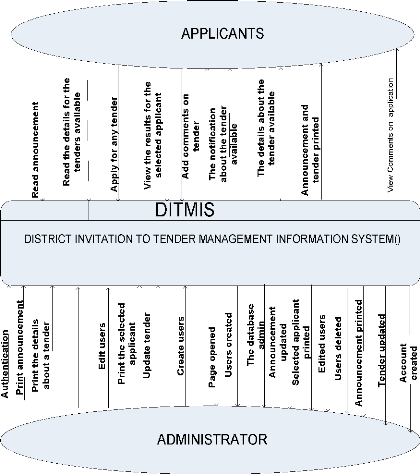
Figure 4. 2: District invitation to tender management
information system context Diagram / Level 0
Source: own drawing
4.3.6.3.Level1DataflowDiagram
Admin
File downloaded
Print announcement
Successfully printed
Admin page displayed
|
Account created
|
Details printed
|

Print details for tender
Create
Download file
Login
administrator's
account
Print
announcement
Print details for tender
6 DITMIS
Upload files
D1
files

Tender file
Administrator's account
D2
D4
Announcement file
Files uploaded
Upload files
Announcement result
Read announcement
D9


Applicant
Display applications
View applications

8

D7
|
|
Application accepted
|
|
Comments file
|
|
|
|
|
Apply for atender

DITMIS

10
Admin
Applicant
Application file
Display selected appliants
View selected applicants
Session closed
Session_close request
D3 Administrator's account
file
5 DITMIS
View appications
D5
7
DITMIS
View comments
DITMIS
Logout
Application for tender file

Apply for a tender

View selected applicant
D10 selected applicant file
Figure4.3 Level1 Data flow diagram Source Own drawing
4.3.6.4 DITMIS List of Tables
Announcement
Announcement_id Announcement_Name Announcement
Announcement_Date
Tender
Tender_id Tender_Name Tender Tender_date
Comment
|
Comment_id Name
E_mail
Address Comment
|
Password
User_id First_name Last_name Password Access_level Level_number
E_mail
|
|
Users
|
|
Results
|
|
|
User_id First_name Last_name Password Re_enter pas sword
E_mail
|
|
Id
Names Address Quantity Price
Details Date
District
|
|
|
|
Applicant2
|
Applicant_id Announcement_id Names
Telephone Occupation\ Address
Quantity
Price
Duration Account_no Bank
Date
|
Table: 4.2 .DITMIS _ List of Tables Source: Own
drawing
4.3.6.5 ER-Diagram
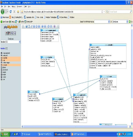
Figure 4.4 E R Diagram Source: Own drawing
4.3.7 Tools Used
+ HTML (Hypertext Mark-up Language)
HTML, an initialism for Hypertext Mark-up Language, is the
predominant markup language for web pages. It provides a means to describe the
structure of text-based information in a document by denoting certain text as
links, headings, paragraphs, lists, etc. and to supplement that text with
interactive forms, embedded images, and other objects. HTML
is written in the form of "tags" that are surrounded by angle brackets. HTML
can also describe, to some degree, the appearance and semantics of a document,
and can include embedded scripting language code (such as JavaScript) that can
affect the behavior of Web browsers and other HTML processors.
(Retrieved June 19.2009 from t
http://en.wikipedia.org/wiki/HTML)
+ CSS (Cascading Style Sheets)
Cascading Style Sheets (CSS) is a style sheet language used to
describe the presentation (that is, the look and formatting) of a document
written in a markup language. Its most common application is to style web pages
written in HTML and XHTML, but the language can be applied to any kind of XML
document, including SVG and XUL.
(Retrieved June 19.2009 from
http://en.wikipedia.org/wiki/Cascading_Style_Sheets
) + Php
PHP is a scripting language originally designed for producing
dynamic web pages. It has evolved to include a command line interface
capability and can be used in standalone graphical applications.
(Retrieved June 19.2009 from http://www.php.net/ ) + Java
Script
JavaScript is a scripting language used to enable programmatic
access to objects within other
applications. It is primarily used in the
form of client-side JavaScript for the development of
dynamic websites.
JavaScript is a dialect of the ECMAScript standard and is characterized as a
dynamic, weakly typed, prototype-based language with
first-class functions. JavaScript was influenced by many languages and was
designed to look like Java, but to be easier for non-programmers to work
with.
(Retrieved June 19.2009 from
http://en.wikipedia.org/wiki/JavaScript)
+ Mysql
MySQL is a relational database management system (RDBMS) which
has more than 6 million installations. The program runs as a server providing
multi-user access to a number of databases.(Retrieved June 19.2009 from
http://en.wikipedia.org/wiki/MySQL)
+ Adobe Flash
Adobe Flash (previously called Macromedia Flash) is a
multimedia platform originally acquired by Macromedia and currently developed
and distributed by Adobe Systems. Since its introduction in 1996, Flash has
become a popular method for adding animation and interactivity to web pages.
Flash is commonly used to create animation, advertisements, and various web
page components, to integrate video into web pages, and more recently, to
develop rich Internet applications.(Retrieved June 19.2009 from
http://en.wikipedia.org/wiki/Adobe_Flash)
+ Adobe Photoshop
Adobe Photoshop, or simply Photoshop, is a powerful graphics
editing program (also known as a DPP, Desktop Publishing Program) developed and
published by Adobe Systems. It is the current and primary market leader for
commercial bitmap and image manipulation software, and is the flagship product
of Adobe Systems. It has been described as "an industry standard for graphics
professionals and was one of the early "killer applications" on the PC.
(Retrieved June 19.2009 from
http://en.wikipedia.org/wiki/Adobe_Photoshop
)
+ Adobe Dreamweaver
Adobe Dreamweaver (formerly Macromedia Dreamweaver) is a web
development application originally created by Macromedia, and is now developed
by Adobe Systems, which acquired Macromedia in 2005.
(Retrieved June 19.2009 from
http://en.wikipedia.org/wiki/Adobe_Dreamweaver/)
+ Apache
The Apache HTTP Server commonly referred to as Apache, is a
web server notable for playing a key role in the initial growth of the World
Wide Web. In 2009 it became the first web server to surpass the 100 million web
site milestone.
(Retrieved August 7.2009 from
http://en.wikipedia.org/wiki/Apache)
4.3.8 Data Dictionary
Data dictionary is that part of database management system that
defines the structure of user data and how they are to be used.
Data dictionary of our system is represented in the following
tables. 1) Applicant2
Field Type Collation Attributes Null Default Extra
Applicant_Id Int(2) - No - Auto_increment
|
Tender_id Announcement_Id Names
Telephone Occupation Address
Quantity
Price
|
Int(11)
Int(2) Varchar(50 Varchar(50 Varchar(50 Varchar(50 Varchar(50
Varchar(50
|
|
|
No
|
-
|
-
|
|
-
|
No
|
|
|
|
Lattin1_general_ciLatin1_general_ciLatin1_general_ciLatin1_general_ciLatin1_general_ciLatin1_general_ci
|
|
No No No No No No
|
|
|
Duration Varchar(50) Latin1_general_ci No
Accoumt_no Varchar(50) Latin1_general_ci No
Bank Varchar(50) Latin1_general_ci No
Date Date Latin general ci No
Table 4.3. Applicant table Source Own drawing
2) Announcement
Field Type Collation Attribute Nul Defaul Extra
s l t
Announcement_id Int(2) No Auto_increme
nt
Announcement_Na Varchar(5 Latin1_general_ No
me 0) ci
No
Announcement Varchar(5 Latin1_general_
0) ci No
Announcement_Dat
e Varchar(5 Latin1_general_
0) ci
Table 4.4 Announcement
Source:
Own drawing
3) Chat
Field Type Collation Attributes Null Default Extra
User_id Int(2) No Auto_increment
Name Varchar(50) Latin1_general_ci No
Message Varchar(50) Latin1_general_ci No
4) Comment
Field Type Collation Attributes Null Default Extra
Comment_id User_id
Name
E_mail Address Comment
|
Int(2)
Int(11) Varchar(20) Varchar(20) Varchar(20) Varchar(20)
|
Latin1_general_ciLatin1_general_ciLatin1_general_ciLatin1_general_ci
|
No No No No No
|
Auto_increment
|
|
Table 4.6 : Comment Source: Own drawing
5) Password
Field Type Collation Attributes Null Default Extra
|
User_id First_name Last_name Password Access_level Level_number
E_mail
|
Int(2) Varchar(20) Varchar(20) Varchar(20) Varchar(20)
Varchar(20) Varchar(20)
|
Latin1_swedish_ciLatin1_swedish_ciLatin1_swedishl_ciLatin1_swedishl_ciLatin1_swedishl_ciLatin1_swedishl_ci
|
No No No No No No No
|
Auto_increment
|
Table 4.7: Password Source: Own drawing
6) Results
Field Type Collation Attributes Null Default Extra
Id
Names Address Quantity Price Details Date District
|
Int(2) Varchar(20) Varchar(20) Varchar(20) Varchar(20) Longtext
Date
Varchar(20)
|
Latin1_general_ciLatin1_general_ciLatin1_general_ciLatin1_general_ciLatin1_general_ciLatin1_general_ciLatin1_general_ci
|
Auto_increment
|
|
Table 4.8: Results Source: Own drawing
7) Attachfile
Field Type Collation Attributes Null Default Extra
|
Attach_id
Applicant_id Bordereau
Lettre
Photocopie
Le_delaiAttestation
Icyemezo_ko_nta_mwenda Icyemezo_ko_yaguze Icyemezo_cy'_ingwate
Date
|
Int(11) Int(11) Text Text Text Text Text Text Text Text
date
|
Latin1_general_ciLatin1_general_ciLatin1_general_ciLatin1_general_ciLatin1_general_ciLatin1_general_ciLatin1_general_ciLatin1_general_ciLatin1_general_ci
|
No No No No No No No No No No No
|
None None None None None None None None None None None
|
Auto_increment
|
4.3.9 Implementation 4.3.9.1 Screen
Glossary
Screen number Screen name Purpose
MAIN PAGE
1.1 Login area This area, allow to login in account as
administrator.
1.2 Home area Informs about the district invitation to tender
management information system (DITMIS).
1.3 Announcement Informs about the announcement on tenders
area available in the district.
1.4 Tender area Informs about the details about the tenders
and it allows also to apply for any tender.
1.5 Contact us
1.6 Login here area
1.7 Register here
1.8 Chat area
1.9 Add comment area
Informs about the contact of the district.
Allows to login as an existing user.
Allows to register as a new user.
Allows members and users of the system to send each other
message.
Allows sending any comment about the system and tenders.
SYSTEM ADMINISTRATOR INTERFACE
2.1 View all applicants
2.2 View all comments
2.3 View all users
2.4 Print announcement
2.5 Print tender
2.6 Create Account
2.7 View attached file
2.8 Logout Allows viewing all applicants.
Allows viewing all comments.
Allows viewing all users.
Allows printing announcement for any tender.
Allows printing the details about the tender available.
Allows to create accounts
Allows to view other additional files attached by applicants.
Allows to quit the administrator interface.
Table 4.10: Screen Glossary Source: Own drawing
4.3.9.2 Sample Interfaces
In this section, sample interfaces are displayed. And the main
functionalities of the system are shown .We displayed the interfaces for the
users in general and also the interface for an administrator to accomplish
their activities.
43
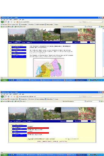
Figure 4.5: The main Page
Figure 4.6: Announcement page
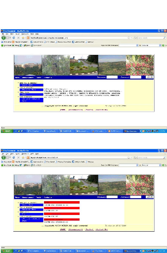
Figure 4.7: End of announcement page
Figure 4.8: The tender page
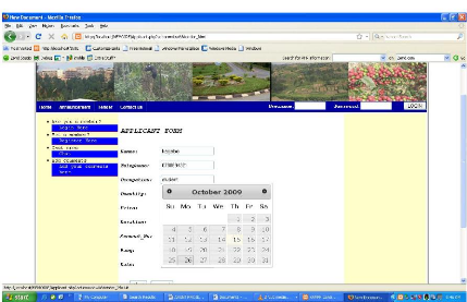
Figure 4.10: The applicant page
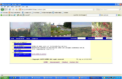
Figure 4.9: The Details for tender page
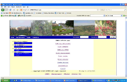
Figure 4.12: The administrator page.
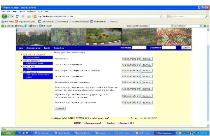
Figure 4.11: the page for uploading other
files.
47
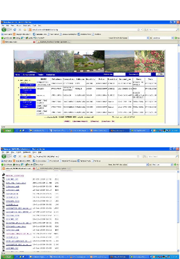
Figure 4.13: The View all applicants page
Figure 4.14: The page for all files uploaded.
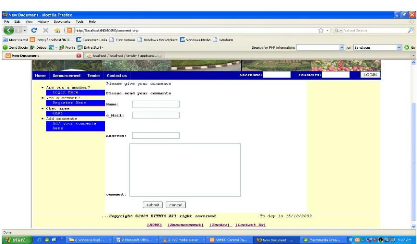
Figure 4.15: The page for submitting a
comment.
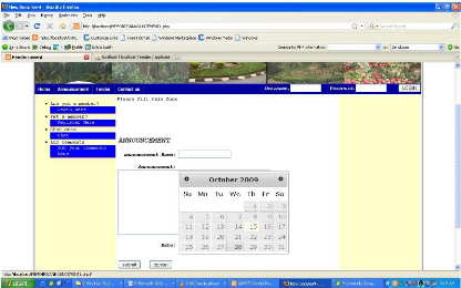
Figure 4.16: The page for printing an
announcement.
CHAPTER 5: CONCLUSION AND RECOMMENDATIONS
5.1 Conclusion
This research aimed at showing the importance of using the web
based system in the improvement of good governance. Based on results of our
research, the goals and the scope of the project it have deduced the conclusion
below:
During the investigation it was found that even if there is
use of ICT in Rwandan Districts, they do not maximize the benefits of ICTs for
their daily activities .Some activities are still not automated because they
have been made manually.
That is why the use of ICT need to be improved through a web
based system that facilitates to keep people get informed on tenders processes
in Rwandan Districts.
Beyond investigation research system development methodologies
were used:
· Context diagram
· System outline
· Data flow diagram
· Entity relationship diagram and
· Data dictionary.
This method helped us to clarify how data are treated in the
current system and how the new system would be .By implementing the
application, it has been found that problems of getting information online on
tenders available in Rwandan Districts and the opportunity for application have
been attended via the use of system called District Invitation to Tender
Management Information System.
DITMIS design has got the benefits as it facilitates citizens to
get all information on tenders available in Rwandan Districts and the
opportunity to apply for any tender.
5.2 Recommendations
Based on experiences, investigation carried out and some
constraints accoutered, to finish this research the following recommendations
are mentioned, for the great success of the present system:
.. The project ended with software product .The wisdom of
software engineering teaches that software is never completed .Thus; we suggest
this software to be considered as «prototype».
.. Some imperfections must be revised and corrected before the
deployment and functionality of DITMIS.
.. The Districts must sensitize the citizens on the use of the
new technology with the aim of improving this system.
.. The districts should provide adequate computer tool, including
the internet to citizens in order to allow them to use the DITMIS.
5.3 Future work
Lastly, the further research should also be done on the
selection of applicants in order to found out the selected applicant based on
the requirements for the application and the contract signed between the
District and the selected applicant.
Bibliography
a) Books:
1. GERAL V .POST «Database Management Systems,
Designing and Building Business Applications «, 1st edition,
P34.
2. PRESCOTT, M, & ALL» Modern Database
Management», 5 edition, Addison Wesley Lonman, Inc, May
1999.p 4.
3. RIHARD, T. WATSON,» DATA MANAGEMENT:
Databases and Organization «, 3rd edition .p25.
4. NSENGIYUMVA JEAN BAPTISTE, HABIYAREMYE ALOYS,
«E-census Web Based Application case of National Institute of
Statistics of Rwanda», February 2007.
b) Web references:
5. http: //
en.
Wikipedia.org/wiki/Data.
6 .http:/ en .wikipedia.org/wiki/system.
7. http:/ www .webopedia.com/ TERM/C/Computer system.html.
8. http;/
www.wikipedia.org/wik/information
system .
6. http:/
www.wikipedia.org/wik/information
technology.
7.
http:// publib. Boulder./
bm.com / infocenter/db2/MW/V8/index.jsp?
topic=/com./bm.db2.vdb. olap .doc/cmd attribute. htm.
8.
http://en.wikipedia.org/wiki/Row
.
9. http:// databasev.co.uk/ primary-
foreign-key-constraints.html.
10.
http://www.dbnormalization.com
/database-anomalies.
11.http://www.databasev.co.uk/ data-redundancy.html.
12.
http://en.
wikipedia.org/wiki/Normal forms.
13.
http://wikipedia.org/wiki/Database-management-system.
14.
http://wikipedia.org/wiki/Data-architecture
.
15.
http://en.wikipedia.org/wiki/Computer-Network.
16.
http://en.wikipedia.org/wiki/Internet.
18.
http://www.softpanorama.org/SE/software_life_cycle_models.shtml
.
20.
http://en.wikipedia.org/wiki/Waterfall_model.
21.www.site.uottawa.ca/school/research/lloseng/supportMaterial/slidesedition1/htmlSlides/Chapter11/tsld009.htm
22.
http://www.softpanorama.org/SE/software_life_cycle_models.shtml.
23.
http://en.wikipedia.org/wiki/HTML.
24.
http://en.wikipedia.org/wiki/Cascading_Style_Sheets
. 25.
http://www.php.net.
26.
http://en.wikipedia.org/wiki/JavaScript.
27.
http://en.wikipedia.org/wiki/MySQL.
28.
http://en.wikipedia.org/wiki/Adobe_Dreamweaver.
29.
http://en.wikipedia.org/wiki/Apache.
30.
http://en.wikipedia.org/wiki/Adobe_Flash.
31.
http://en.wikipedia.org/wiki/Adobe_Photoshop
.
| 
