CHAPTER III: RESEARCH METHODOLOGY
3.1 Introduction
The third chapter states the methodology used to reach the
objectives of the
project. The framework in which software is designed,
developed, and maintained is known as the Software Development Life Cycle
(SDLC). It shows the steps, phases, milestones, and evolution of the software
development process. There are many types of models used in software design and
development. Among them are the spiral models, rapid development model,
Evolutionary model, waterfall model, prototyping model, etc.
3.2 Prototyping model
Prototyping Model has been used to develop this application. The
Prototyping11
model is a technique for quickly building a function but
incomplete model of the information system.
3.3 Advantages of prototyping
· Reduces development time.
· Reduces development costs.
· Requires user involvement.
· Developers receive quantifiable user feedback.
· Facilitate system implementation since users know what to
expect.
· Results in higher user satisfaction.
· Exposes developers to potential future system
enhancements.
3.4 Disadvantages of prototyping
· Can lead to insufficient analysis.
· Developers can become too attached to their
prototypes.
· Can cause systems to be left unfinished and/or
implemented before they are ready.
11 Whitten Bentley, «Systems analysis and design
methods 7th edition», p.70
3.5 The process of prototyping
> Identify basic requirement: Determine
basic requirements including the input and output information desired. Details,
such us security, can typically be ignored.
> Develop initial prototype: The initial
prototype is developed that includes only user interfaces.
> Review: The customers, end-users, examine
the prototype and provide feedback on additions or changes.
> Revise and enhancing the prototype: Using
the feedback, both the specifications and the prototype can be improved.
This method involves a series of iterations and refinement until
the prototype product is a fully working system, and the user is satisfied.
3.6 Prototype cycle
Startin


Timing

Figure 5: Prototype Cycle
Source: Own drawing using Ms Visio

This prototype model usually consists of the following: >
Analyze the users' basic requirements.
> Repeat
o Develop or revise the working prototype to
include the requirements that are known at this stage.
o Allow the user to use the prototype to
suggest changes to the requirements. If there are no major changes, exit the
loop.
o Analyze the requested changes with the
user.
The outcome is usually one of the following:
> The final prototype is used as part or all of the
specifications for the
formal development of the system.
> The final prototype is placed into production.
3.6 The importance of using prototyping
It has been argued that prototyping, in some form or another,
should be used all
the time and is very effective in the analysis and design of
on-line systems, especially for transaction processing, where the use of screen
dialogs is much more in evidence. However, prototyping is most beneficial in
systems that will have many interactions with the users. Prototyping is
especially good for designing good human-computer interfaces.
3.7 Analysis of the system
The initial step while developing an application program
consists exactly to find
out what to be solved and what should be done and to make
sure that the measures taken are consistent and sufficient to resolve the
problem. It also consists of finding out what are the requirements
specifications that the system will use, who are the users, what is the benefit
of the application, those activities are done to help full system analysis
3.7.1 The existing system
There is no any other automated product at Kigali International
School. The
current system is manual. They use Ms Excel, which is so
difficult to use, where the user must memorize all features of the tool and
this is not easy and results to different errors.
3.7.2 The proposed system
While analyzing the existing system, the automated system has
been proposed.
This is the School Management System. It allows the user to
store data, retrieve data and manage simply. Secretary can insert teachers'
information, course information, distribute courses among available teachers,
inform all teachers for changes and other related to school activities
3.7.3 System requirements
Ubuntu Linux Operating system revealed itself as a product of
choice because of
viruses' issue, but that product can also run under Windows
XP, Vista as Operating System, Processor 2.5 GHz and 1014 MB RAM and 60 GB Hard
Disk for each machine.
3.8 System Actors
System actor is any person who will use or affected by an
information system on
a regular basis-capturing, validating, entering, responding
to, storing and exchanging data and information. The School Management System
has two categories of the system users. They are:
· School Secretary.
· System Administrator.
3.8.1 Actor glossary Table 1: Actor Glossary
|
User
|
Activities
|
|
School Secretary
|
The school staff in charge of planning courses, teachers,
modification of those entries if necessary
|
|
System administrator
|
Creates system new users, modify user
or delete user, creates
and publish
news and announcements, view all
information in the system
|

PROCESS
ü Adding courses
ü Registering teacher
ü Section registration
ü Class registration
ü User registration
ü View all Information
ü Course planning
ü Time calculation
3.8.2 System outline
|
INPUT
ü Request for Adding course
ü Request for registering a teacher.
ü Request Section
registration
ü Request Class registration
ü Request User registration
ü Request information
|
|
FILES
ü Courses file
ü Teachers file
ü Classes file igre: System
ü Users file
ü Section file
ü Announcement and news file
|
OUTPUT
ü Show all courses
ü Show all teachers
ü Show all section
ü Show all classes
ü Show all news
ü Show all announcements
ü Confirmation message
ü Error message
|
|


Figure 6: System outline
Source: Own drawing
3.9 Data flow diagram
A data flow diagram concentrate upon the data needed to support
the information
requirements of the system.
What is needed, what the processes that convert it? It provides
the notion of structure, static pieces of documentation, communication
tool...
3.9.1 Dataflow notations
A DFD has 4 keys components
Table 2: Dataflow notations
|
External Entity: exist in the system's
environment and either provide data to the system (sources) or
receive data from the system (sinks).
|
|
Process: The individual task which when
completed in a certain sequence fulfils the overall goal of
the system of which is a part. It transform input into output
|
|
|
|
|
|
|
|
Data store: contains data which is needed by a process in order
for it to be completed
|
|
|
|
|
Data Flows: Depict the fact that some data in the form of
documents is moving from an external entity to a process or vice versa, from
one process to another, from a process to a store or vice versa.
|
|
|
3.9.2 Context Diagram
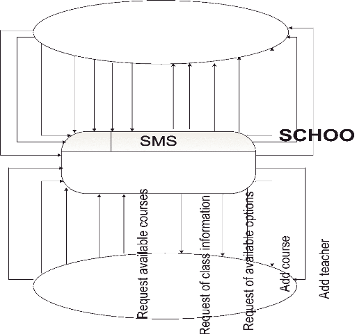
Figure 7: Context Diagram
Source: Own drawing
The figure above shows the interaction between the system and
external agents which act as data sources and data sinks. The context diagram
shows the entire system as a single process, and gives no clues as to its
internal organization.


3.9.2.1 Data Flow Diagram Level 0
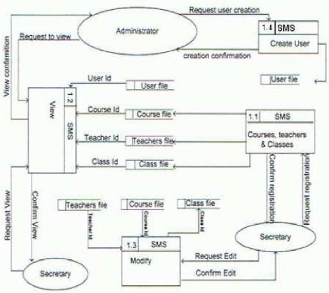
Figure s: DFD level 0
Source: Own drawing
The figure above shows how the system users intervene with the
process of the school management system for teachers, courses and how data are
sent into different Data files. It shows in general how users interact with the
system and how data are being processed to respond the user request.
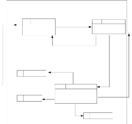
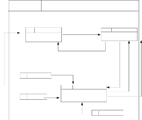
3.9.2.2 Data Flow Diagram for School Secretary/
Register
Request information to register
1.1.1 SMS/R/RD
Teacher
Register data(Teacher,
Course, class)
class
1.1.3
Registration transimission
Field verification
SMS/R/RT
Data
course
1.1.2
Check data
SMS/R/CD
Send information
Confirm registration
Figure 9: DFD level 1/ Registration
Source: Own drawing
The Figure above shows how secretary interact with the system to
process registration of courses, teachers and classes.
3.9.2.3 Data Flow Diagram for School Secretary/
View
Request of viewing
Course id
Send information
Return information
Confirmation of Viewing
Figure 10: DFD level 1/ View
Source: Own drawing
The figure above shows the way for secretary to view all
information necessary .

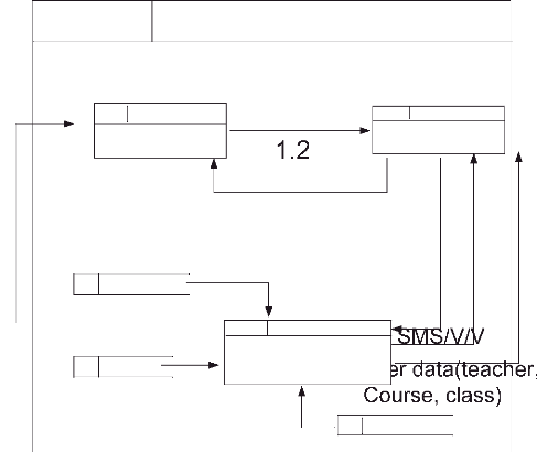
3.9.2.4 Data Flow Diagram for Secretary/ Edit
Request of viewing
1.3
1.3.1
teacher
Register data(teacher,
Course, class)
class
SMS/M/Inf
teacher id
Class id
1.3.3
Providing information
Confirmation
SMS/M/MD
SMS/M
Modify data
Course id
course
1.3.2
Request information
SMS/M/RI
Send information
Return information
Figure 11: DFD level 1/ Edit Source: Own
Drawing
The figure above explains how secretary interact with the system
to edit data where necessary.
3.9.2.5 Data Flow Diagram for System Administrator/
Create User
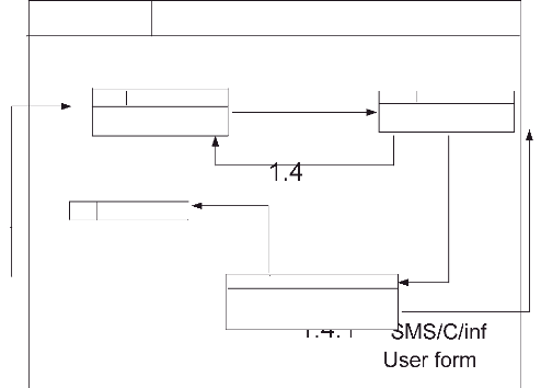
Rea uest user creation
User information
User information
User creation confirmation
Figure 12: DFD level 1/ User creation
Source: Own drawing
The figure above shows the process of creating user, and here the
user said is school secretary. This task is performed by System
administrator.

3.9.3 Entity Relationship Diagram of SMS
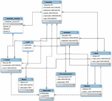
Figure 13: Entity relationship
Source: SMS
The figure above shows the tables in SMS Database, how the
relationships between entities are created. This graphic is made by using MYSQL
Workbench and are normalized to remove some anomalies. Rectangles represent
entities; the entity name is placed at the top and the attributes at the
bottom.
| 

