Table of Contents
GENERAL INTRODUCTION
4
CHAP1: STATE OF THE ART 10
1.1 INTRODUCTION
10
1.2. STUDY OF THE CURRENT SITUATION
10
1.3. DESCRIPTION OF THE EXISTING
10
1.4. PROJECT PRESENTATION
12
1.4.1. PROVIDED SERVICES
12
1.4.2. PROVIDED FEATURES
13
1.5 METHODOLOGY OF DEVELOPMENT
14
1.5.2 V-CYCLE MODEL
15
1.5.3 SPIRAL MODEL
16
1.5.4 CHOSEN METHODOLOGY
17
1.6. CONCLUSION
17
CHAP2: SPECIFICATION AND ANALYSES OF NEEDS
19
2.1 INTRODUCTION
19
2.2 SPECIFICATION OF THE NEEDS (FUNCTIONAL AND NON
FUNCTIONAL)
19
2.2.1 FUNCTIONAL NEEDS
19
2.2.2. NON FUNCTIONAL NEEDS
20
2.3. ACTORS
21
2.4. USE CASES
23
2.4.1. USE CASES BY PRIORITY
23
2.4.2 INTERACTIONS ACTORS /SYSTEM
24
2.4.3. USE CASE DIAGRAMS
29
2.4.4. USE CASE DIAGRAM: DETAILED TEXTUAL
DESCRIPTION
31
2.4.4.1 CONDUCT OF USE CASE: ACTIVITY DIAGRAM
31
TEXTUAL CASE SCENARIO "AUTHENTICATION"
31
TEXTUAL CASE SCENARIO "CONSULT PRIVILEGED
SPACE"
32
TEXTUAL CASE SCENARIO "SEARCH DOCUMENT"
33
TEXTUAL CASE SCENARIO "REGISTER FOR TRAINING"
35
2.4.4.2. DIAGRAM OF SEQUENCES SYSTEM
37
TEXTUAL CASE SCENARIO "REQUEST FOR
REGISTRATION"
39
TEXTUAL CASE SCENARIO "PROPOSE ONLINE TEST"
40
2.7.2 REGISTER FOR TRAINING
41
2.8. CONCLUSION
42
CHAP3: DESIGN 44
3.1. INTRODUCTION
44
3.2. ARCHITECTURAL CONCEPTION
44
3.2.1. TECHNICAL ARCHITECTURE
44
3.2.2 LOGIC APPLICATION ARCHITECTURE
(THREE-LAYER)
45
3.2.2.1 PRESENTATION LAYER
46
3.2.2.2 BUSINESS LOGIC LAYER
46
· SERVICES LAYER
46
· BUSINESS OBJECTS
46
3.3. DETAILED DESIGN
47
3.3.1. DESIGN PATTERN
47
3.3.1.1. MVC
47
3.3.1.2. DAO
48
3.3.1.2. SESSION FACADE
50
3.3.2 PACKAGES DECOMPOSITION
52
3.3.3.2 MODELS PACKAGE
53
3.3.3.2 SESSION BEANS PACKAGE
55
3.3.3.3 CONTROLLER PACKAGE
55
FUNCTIONAL STRUCTURE OF THE APPLICATION
56
3.3.4 INTERACTION DIAGRAM
56
3.4 CONCLUSION
57
CHAP4: IMPLEMENTATION 59
4.1 INTRODUCTION
59
4.2 WORKING ENVIRONMENT
59
4.2.1 HARDWARE ENVIRONMENT
59
4.2.2 SELECTION OF PROGRAMMING
LANGUAGE
59
4.2.1
J2EE TECHNOLOGIES IMPLEMENTS 3-TIER ARCHITECTURE
59
4.2.2.1 JSF: JAVA SERVER FACES TECHNOLOGY
60
4.2.2.2 JPA: JAVA PERSISTENCE API TECHNOLOGY
60
4.2.2.3 EJB: ENTERPRISE JAVA BEANS
60
4.2.3 SOFTWARE ENVIRONMENT
61
4.2.3.1 NET BEANS TECHNICAL REASONS
61
4.2.3.2 CHOICE OF MYSQL
62
4.3 DEPLOYMENT DIAGRAM
62
4.3.1 APPLICATION INTERFACES
62
4.5 IMPLEMENTATION
63
4.6 TIMING DIAGRAM
63
4.7 CONCLUSION
65
GENERAL CONCLUSION
66
NETOGRAPHY
68
LIST OF FIGURES
FIG2. WATERFALL MODEL
4
FIG2. V-CYCLE MODEL
16
FIG3. SPIRAL MODEL 17
FIG4. ADMINISTRATOR USE CASE DIAGRAM
30
FIG5. VISITOR USE CASE DIAGRAM
4
FIG6. TEACHER USE CASE DIAGRAM
31
FIG7. STUDENT USE CASE DIAGRAM: STUDENT
4
FIG8. ACTIVITY DIAGRAM: AUTHENTICATE
32
FIG9. ACTIVITY DIAGRAM: CONSULT PRIVILEGED
SPACE 34
FIG10. ACTIVITY DIAGRAM: SEARCH
DOCUMENT
4
FIG11. ACTIVITY DIAGRAM: REGISTER FOR
TRAINING
37
FIG12. SEQUENCE DIAGRAM: UPLOAD
DOCUMENT
38
FIG13. SEQUENCE DIAGRAM: REQUEST FOR
REGISTRATION
40
FIG14. SEQUENCE DIAGRAM: PROPOSE ONLINE
TEST
41
FIG15. SEQUENCE DIAGRAM: REGISTER FOR
TRAINING
42
FIG16. N-TIER TYPE ARCHITECTURE
44
FIG17. LAYERS OF THREE-TIER LOGIC
ARCHITECTURE
45
FIG17. MODEL-VIEW-CONTROLLER
47
FIG18.DATA ACCESS OBJECT CLASS DIAGRAM
49
FIG19. SESSION FACADE CLASS DIAGRAM
51
FIG20. PACKAGE DIAGRAM
53
FIG21. MODELS PACKAGE: CLASS
DIAGRAM
54
FIG22. SESSION BEANS PACKAGE: CLASS
DIAGRAM
55
FIG23. MANAGEMENT PROCESS PACKAGE: CLASS
DIAGRAM
56
FIG25. FUNCTIONAL STRUCTURE OF THE
APPLICATION: USER-SIDE
56
FIG 26. SEQUENCE OBJECTS DIAGRAM
57
FIG27. TYPICAL EXAMPLE OF A
J2EE ARCHITECTURE
61
FIG28. DEPLOYMENT DIAGRAM
62
FIGURE 29.
USER AUTHENTICATION INTERFACE
63
FIGURE 30. FORUM INTERFACE
63
FIGURE 31. MANAGEMENT
INTERFACE
63
FIG32. GANTT DIAGRAM (SEQUENCING TASKS /
TIME)
65
LIST OF TABLES
TAB1. COMPARISON BETWEEN
LIFECYCLE-MODELS
4
TAB2. USE CASES BY PRIORITY
4
TAB3. USE CASES: GENERAL TEXTUAL
DESCRIPTION
4
TAB4. AUTHENTICATION SCENARIO
4
TAB5. CONSULT PRIVILEGED SPACE SCENARIO
4
TAB6. SEARCH DOCUMENT SCENARIO
4
TAB7. REGISTER FOR TRAINING SCENARIO
4
TAB8. UPLOAD DOCUMENT SCENARIO
4
TAB9. REQUEST FOR REGISTRATION SCENARIO
4
TAB10. PROPOSE ONLINE TEST SCENARIO
4
Appreciation
I thank God firstly for allowing
me to complete this project that is for
me the starting point of an interesting adventure, for
research, development and improvement.
Allow me to pay
tribute to my project supervisor, Mr Gharbi Sofiène
for supervising this work and given
his time and intelligence to the success of
this modest project, and Mr Cherni Thameur for his help and availability
to correct this report.
I
take this opportunity to thank those who have given
me their contribution, whether at the level of ideas or design. There
is here to express my sincere recognition.
Finally I thank the jury
members who have kindly accepted to perform
evaluation of this modest work.
Dedication
I dedicate this work
to who without his help I couldn't achieve this
work: my husband Ali.
For his care he has always give to me.
General Introduction
Computers are increasingly present in our everyday life; when we
say computer we say information, electronic documents, knowledge, etc.
There are now about these services offered which have become
indispensable the functioning of the computer tools and information systems.
There are a set of constituent elements interacting with each
other, and transforms inputs into outputs, a set of methods that allow
treatment information within an organization and its environment. These key
features are; information gathering, storing, processing and dissemination. So,
for any of these systems, it is essential to study, understand and control its
operation.
After this study and to ensure that these services will be
beneficial and optimal, it is necessary to manage all the information,
documents, and system users to simplify their use.
That's why most companies and institute have automated their work
with the software integration. Similarly, there is a pressing need to automate
many Esprit activities. This requires the design and implementation of a
knowledge base that should be a central site to store information and provide
space to answer frequent queries. It also should provide search engine to help
users find the appropriate article matched with their query.
This type of system is a very handy tool working in a narrow
domain to provide answers for frequently asked questions and should be easily
addressed by any user.
Knowledge is acquired and represented using various
representation; techniques of knowledge rules, frames and scripts. The basic
advantages offered by such system are documentation of knowledge, intelligent
decision support, self learning, reasoning, explanation and many other features
that can be added. We can't forgot also that the collaborative work, sharing
and data document transfer is very interesting for each institution or company;
so a knowledge base is essential such for students or clients.
In this stage our intervention is to design and implements the
Esprit Knowledge Base; following methodologies and best practices to provide
these modules:
Interact in the forum, consult library, upload / download
documents, register for training, pass assessment tests online, receive all
school news, consult the address book, view files and shared documents, write
articles or comments, consulting his traces...
Other main modules to the
system administrator like overseeing general site operations: as user,
documents or library management, forum management and dashboard of teacher's
skills.
Thus, for a better organization of the work, and to achieve our
goals we rely on a well structured approach containing four parts each one
contains a chapter divided as follows:
The first
chapter is devoted to the state of the art: it is the state of existing
knowledge related with our subject. It contains a study of art, existing
issues, some problems solutions and chosen process methodology.
The second
one deals with the case study that helped to discover end-user and
organizational requirements that formed the basis of the development of our
system; it analysis actor's identification, functional and non-functional
requirements, activity and sequence diagram to represent general collaborations
between objects and system according to the chronological order.
A third will contain the classes' diagram, to formalize the
preliminary stages of development that will be explained in the last chapter.
It will lead tools for implementation, code optimization, validation test and
explains the underlying reasons for choosing these techniques and tools.
The conclusion at the end of this report will list the
achievements and limitations of the system and the future possibilities.
State of the art
Chapter 1
State of the art
1.1 Introduction
The state of the art aims to seek what are general information
and publications related with methods of design and development of a knowledge
base and the main features it has to offer. It's the preliminary step to our
project. So it is necessary:
§ To search beneficial information related to this
topic.
§ To be aware of the environment: find more information,
methods and standards used in this field; this helps to broaden the subject.
§ To define areas of research, from knowledge of the
environment: it will explain how to apply current knowledge to its needs.
1.2. Study of the current
situation
As already said, this study will allow us to
know more from knowledge base operations and reach some common features between
all these systems that are no longer mandatory and must be presented in first
step of conception and development. There are two principal functions: document
search and information sharing.
And the other basic advantages are documentation of knowledge,
intelligent decision support, self learning, reasoning and explanation.
1.3. Description of the
existing
A study of existing is to look at what already exists; it is from
this study that we can make real progress versus the existent, not to 'create'
something already created in previous works, to overcome their flaws and add
more benefits to our system.
As already said; Knowledge base is a special kind of
database for
knowledge
management, providing the means for the computerized collection,
organization, and
retrieval of
knowledge.
Our own study has provided that there is no knowledge
base to ESPRIT; there is only moodle site that is
missing several features;
The initial design of this
site presents in my opinion many misconceptions
§ Navigation is
via a full-page general index and thus causes an
impractical navigation
§ It doesn't offer a search engine
§ You should register to all courses you want to download
file related with.
§ All other members can see what topics you are registered
to.
§ It displays your real name instead of your pseudo
§ All other members can know if you are connected at the
moment.
§ If a user forgot his
password he can't retrieve it again; he should register
with another login, password and e-mail.
§ News of the institute is not displayed in the site.
§ the site is not updated and this
is possibly returned to the difficult
management of Some units
§ It doesn't have an attractive design.
And many other missing features...
A study was conducted to develop a web knowledge base
Information System that would alleviate all of the problems detected. The
choice of a web-based application was obvious. Esprit has
two universities and aims to create an
entire campus, so it needs to share data across a large distance (using
internet).
One of the other fundamental strengths of the Internet is the
set of standards that define how users connect to servers and how data will be
displayed. We take advantage of the network capabilities of the Internet and
the presentation standards of the World Wide Web. By developing an application
to run on a web site, with ensure of a widest possible compatibility and
accessibility to the system. Users can benefit from their features even if they
are not physically present at the institute (as long as they have access to a
web browser).

We should mention also that since the development of personal
computers, software products produced by development companies have dominated
the market. These products account for the vast majority of software sales and
are usually cheap as the development cost is spread across hundreds or
thousands of different customers. Among these software's; we can mention:

§ Knowledge Base Software

§ Interspire

§ Knowledge base publisher

§ Omnistar knowledge management software
§ PHPkb
The common
point that may be mentioned among all this
software, is that they are developed by well known languages
that we are already studied like php, c, java and they reflect
what they think customer will use. They are generally not flexible and
designed more for businesses than for institutions use.
So a software engineering approach is ideal for manually
developing our Esprit knowledge base;
particularly as we are engineering students,
so with the support of our supervisors
we can design and develop this site from the beginning to
the end without intervention of any knowledge base software.
The specifications for these systems are often the basis for the
contract between customer and contractor. In this project, there is a need to
define all specifications and changes in detail. This
poses no problem because I am an Esprit
student, I present some students segment and my supervisor
will present professor segment.
1.4. Project
presentation
The knowledge based systems are artificial intelligent tools
working in a narrow domain to provide intelligent decisions with justification.
Knowledge is acquired and represented using various knowledge representation
techniques rules and frames.
After this study, we can pick the following services and features
should be presented by our web site:
1.4.1. Provided services
§
Find the Right Message at the Right Time
For quick and easy information found; Smart Synopsis provides
access to the most relevant articles; we should in the first step provide a
search engine that is configurable for article authoring. Attachments can be
added to articles to supplement content and provide context. Instant publishing
and article import flexibility.
§
Seamless Self-Service
Users can help themselves by using an available public portal.
Find Solution to their toughest questions.
§
Services for all users
An
optional visitor registration portal gives you permission access to other
Knowledgebase features.
§
Update and Share Information
Encourage users to contribute
content to Knowledgebase by adding points for each interaction in the forum,
distribute the information using centralized knowledge-sharing services,
continually improving the quality of the application.
§
Facilitate user intervention
Most file formats and documents are accepted so document upload
is quick and simple without format conversion.
1.4.2. Provided features
§ Store text-based data and knowledge as
searchable Knowledge Base articles
§ Store any type of file, application, document as a
file located inside the Knowledge Base or attached to a relevant article
§ Advanced user-rights management with users,
user-groups and passwords
§ Different users can see different parts of the Knowledge
Base according to their privileges
§ Control access to Knowledge Base categories, articles and
files using a security model
§ Centrally and securely located on the WWW hosted on
Web Central servers
§ Accessible from anywhere, anytime, by whoever
privileged
§ Host an online help knowledge for your visitors; answer
for their questions
§ Advanced searching and organization features
means no more wasted time searching for files on local computers or network
drives; procedures and other information is as simple as entering a few key
words.
§ Allow for a large number of people to contribute to and
share stored data
§ Aid in easy storage and retrieval of data
§ Reduce repetitive duplicate input
§ Improve communication between users
§ Using ergonomic and attractive web
interface
For the
site administrator;
§ control exactly what is inside the Knowledge Base using
advanced security profiles and policies
§ Control access to data, based on user roles (defining
which information users or user groups can view, edit, publish, etc.)
§ Define user groups for controlling who has access to what
information
§ Manage all documents, users.
1.5 Methodology of
development
When developing any system, it is recommended to divide it into
tasks or groups of related tasks; it makes it easier to be understood,
organized and managed. In the context of software projects, these tasks are
referred to as phases. Grouping these phases and their outcomes in a way that
produces a software product is called a software process.
There are many different software processes, and none is ideal
for all instances. Each is good for a particular situation and, in most complex
software projects; a combination of these processes is used. The most used life
cycles (processes) for software development are:
§ Waterfall model
§ V model
§ Spiral model
To implement the most appropriate methodology of work, it is
essential to understand how each of these models (waterfall, V and spiral
cycle) operates and what are the differences between them.
1.5.1 Waterfall model
The waterfall model is the oldest and most widely used model in
the software development field. It is based on the following assumption: we
cannot build the roof before the foundation;
There are certain advantages of the waterfall model, which causes
it to be the most widely used model as yet. Some of them can be listed as
under:
§ produce the deliverables defined in advance;
§ to complete in a specific date;
§ Not be completed until the deliverables are satisfactory
in a step-validation check.
§ Needless to mention, it is a linear model and of course,
linear models are the most simple to be implemented.
§ The amount of resources required to implement this model
is very minimal.
§ One great advantage of the waterfall model is that
documentation is produced at every stage of the waterfall model development.
This makes the understanding of the product designing procedure simpler.
§ After every major stage of software coding, testing is
done to check the correct running of the code.
§ Easy to explain to the user
§ Stages and activities are well defined
§ Helps to plan and schedule the project
§ Verification at each stage ensures early detection of
errors / misunderstanding
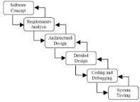
Fig1. Waterfall model
1.5.2 V-cycle
model
This model is an improved cascade model that limit return to
previous steps in case of anomalies. To enhance the software functionalities
the phases of the rising part, must submit information on the phases in other
side when errors are detected.
Further more, the V cycle highlights the need
to anticipate and prepare in stages down the "expected" of future steps rising:
as expected the validation tests are defined in the specifications, the
expected unit tests are defined in the design.
It helps us to manage and coordinate acceptance testing
activities, test defect management, test plan preparation and following
clients' project requirements.
The benefits of performing verification and validation
activities:
§ Improved software quality
§ Improved customer satisfaction
§ Reduced cost of development
§ Reduced cost of maintenance
Verification and validation activities are performed at every
stage of the software development lifecycle as depicted by the V-model
below;
![]()
Fig2. V-cycle model
1.5.3 Spiral model
This development describes the various stages of the V
cycle. By implementation of successive versions, the cycle starts by
proposing more full and hard product.
The spiral cycle emphasis risk management than V-cycle indeed,
the beginning of each interaction includes a risk analysis phase.
![]()
Fig3. Spiral model
1.5.4
Chosen methodology
Tab1. Comparison between Lifecycle-models
|
V-model
|
Spiral model
|
Waterfall model
|
|
+ Well-structured tests
+ Prioritization system to be
developed
- Validation against requirements: very expensive if errors are
found.
|
+ Assessment and risk control
- The number of turns
can be large therefore costly project
+ - Relatively new model
|
+ Well suited for smaller systems as opposed to complex
systems.
+ The tests apply to the overall application.
- Period long
enough to see result.
|
The study and comparison of these models lead us to choose
waterfall model because it is well suited for small systems, it offer
an approach to risk reduction, minimizing the impact of uncertainties. This
impact in the development phase is lower than the impact of uncertainty in the
phases of design or specifications, the more the project progresses, the risk
decreases. Unlike the spiral model that is designed for large systems whose
needs are changing and V-model which is very risky if errors are found.
So, throughout the rest we must follow these steps: Analyze,
design, program development, testing and implementation.
1.6. Conclusion
Our project is a helpful tool that facilitates
communication, learning and sharing knowledge between ESPRIT students, teachers
and other site visitors.
Thus we must specify what our tool will provide, try
to explain it in a sight of a computer expert and to satisfy
user's needs that will be the subject of the next chapter.
Specification and Analyses of Needs
Chapter 2 Specification and Analyses of
the needs
2.1 Introduction
Whether we design an
application we should know what it must present, so we can't progress without
studied and marked the output specifications of our final product.
The process of discovering, understanding, negotiating,
documenting, validating, managing the set of requirements and project
requirement specification for the web-based system should be accomplished
through this chapter. If the software that is going to be designed should
contain certain specific features then it is also mentioned in this stage.
2.2
Specification of the needs (functional and non functional)
A requirements specification should provide precise, measurable
and unambiguous details about what the product must give out in general,
without providing unnecessary constraints or suggesting possible solutions.
2.2.1 Functional needs
Functional requirements express an action that performs the
system response to a request (which outputs are produced for a given
set Input).
Our esprit knowledge base should provide all these
features:
§ Functionalities of Adding, updating and deleting
user, block accounts of some users for a defined duration
§ Uploading / downloading updating and delete
documents receives by privileged user
§ list of all documents in a sorted way: show library
§ Adding, updating, deleting and shows the list of
questions and its appropriate answers or
comments and users that makes it..
§ Display / update knowledge Scoreboard of teachers
§ Space to post announcements in the home page (seminars
-training...)
§ organize training
§ post testes in the provided space in the platform
§ download students copies
§ Send the corrected review for registered students.
§ register for training
§ Register to pass online test
§ Shows the personnel file of a user: all the registered
elements of the file must be displayed.
§ Search engine for documents by title / author / subject
/code.
§ Add / remove and count points: for each answer
/comment...
And other functionalities will be presented and explained in the
textual description part.
2.2.2. Non functional needs
All information systems with a certain point in their life cycle
must be considered non-functional requirements and testing. For some projects
these needs will require a very important work and other project areas a quick
check will suffice.
§ security
§ usability
§ reliability
§ interoperability
§ scalability
§ Performance requirement
§ Hardware
§ Deployment
Security needs: Our
application should
§ Contains interface for connection and verify if generated
information are correct.
§ Each user is classified with his
appropriate privileges: each registered user who
will be connected has its own interface.
§ Can define the possible levels of access to system for
system users and external systems.
Ex: Any confidential information provided
by clients will be encrypted with an encryption algorithm
§ Logout after idle time of inactivity or after three false
passwords.
Usability needs:
§ refer to general aspects of the interface Users Eg
standard used
§ Definition of the minimum browser (Web application)
Simplicity: A clear and simple user
interface to handle.
Performance needs: Describe the
execution performance of the system, generally in terms of response time.
§ (web) Download page time: Loading a webpage in the browser
should not take more than 15 seconds in normal condition.
§ Response time: the application loads, opening
times and screen refresh, etc.
§ Processing time- functions, data exports.
§ Initial load time and load data: Interrogation of the
database
Capacity requirements
Memory (Storage) - how much information should the system be able
to store?
Needs of availability /
reliability:
Related to the level of availability that must be
explicitly defined for critical applications
Ex availability requirement
24/24, 7 / 7 except during maintenance (specify
...)
Compatibility
§ Material needs
-define the minimum hardware necessary
to operate the system
§ Compatibility on different operating systems - on which
he should be able to function?
§ Compatibility on different platforms - What are the
hardware platforms to work?
Ergonomics
The ergonomics standards-User Interface, the density of elements
on the screens, the layout and flow, colors, keyboard shortcuts
Documentation
Elements of documentation required to explain how to use the
application.
Deployment needs
describe how the
application will be delivered to End User
ex: All the software on the client
side will be downloaded and installed from the browser, without the position of
the client is restarted or configure.
2.3. Actors
Actors are entities that interact with the system under design.
Answer to the following questions lets us to identify our system actors and
capabilities of each one.
Q- Who is intended to use the
system?
R- Any authenticated user (having the privilege
to connect)
Q- Are they belonging to the same
user type?
R- They are different, picked according
their requirements and classified by privileges and roles given for each
one.
Q- How many users are there?
R- We can't limit the total number or the
maximum number of concurrent users at any one time but there are three sets of
users: ESPRIT students / teachers and some
visitors of the site.
The system will be represented by web interfaces and presents
several features. So it is essential to provide maintainability future
expansion and perhaps some plans for future developments.
Q- Who will maintain the
system?
R- Our system must have an administrator. So the
forth and principal actor is the system administrator.
After we knew the actors we need to know all their functions that
can be attended from our system to clearly identify the use cases.
Q- What for?
R- It will be answered for each actor
separately; since they do not require same services.
System administrator
He controls all the system operations: He is the responsible of
the platform; He/She have the heavy task and deal with the system. His
functions include all these stages:
§ manage users
§ manage documents
§ Control the forum
§ manage table of board of teachers skills
§ post announcements
§ consult the library
§ upload / download documents
§ interact in the forum
§ access to all user interfaces
§ access to his personal directory
Member
users: Members of this user group can accesses their allowed interfaces with
determined tasks. All their updates must firstly be validated by administrator
before publishing, they are teachers and students.
Teacher
§ Organize training
§ propose and correct online quizzes
§ consult the library
§ upload / download documents
§ interact in the forum
§ access to his personal directory
Student
§ pass online assessment tests
§ register for training
§ consult the library
§ upload / download documents
§ interact in the forum
Visitor
This is the group that accesses only to public area. They don't
need authentication, and goes directly to forum space to:
§ interact in the forum
§ request for registration
2.4. Use cases
2.4.1. Use cases by
priority
At this stage we will present all system use cases classified by
their priority:
Tab2. Use cases by
priority
|
Use case
|
Use case id
|
priority
|
|
Manage user
|
uc1
|
High
|
|
Manage document
|
uc2
|
High
|
|
Control the forum
|
uc3
|
High
|
|
Manage dashboard of teachers skills
|
uc4
|
medium
|
|
Post announcement
|
uc5
|
medium
|
|
Consult library
|
uc6
|
High
|
|
Upload / download documents
|
uc7
|
High
|
|
Interact in the forum
|
uc8
|
medium
|
|
Access to his personal directory
|
uc9
|
High
|
|
Organize training
|
uc10
|
medium
|
|
propose and correct online quizzes
|
uc11
|
medium
|
|
Pass assessment tests
|
uc12
|
medium
|
|
Register for training
|
uc13
|
medium
|
|
Request for registration
|
uc14
|
Low
|
2.4.2 Interactions actors
/system
Tab3. Use cases: general
textual description
|
Use case
|
Actor
|
Pre-condition
|
Nominal Scenario
|
|
Manage users
|
administrator
|
* Needs connection establishment.
* The user must authenticate
to the system
(with login and password).
|
Throws: MAJ (Adding, updating and deleting)
user
Receives: list of all users, informations about each
one, list of connected users.
|
|
Manage documents
|
administrator
|
* Needs connection establishment:
* the user must authenticate
to the system
He must have privileges to perform document management.
|
Receives: acquisition document: uploaded by
student or teacher / provided by school
throws:
Index document using its metadata (type, author, title, id, date,
etc.).
Storage: enter the base
Released: get into the site
Send corrected review to each student in his personal
directory.
Receives: list of all documents (sorted
according their code)
|
|
Control the forum
|
administrator
|
* Needs connection establishment: the user must authenticate to
the system
* He must have privileges to manage the forum.
|
Throws:
Add / remove items: for each answer /comment or good
topic.
Getting rid of parasites, block accounts of some users for a defined
duration
improving access and sharing information: suggest topics for
discussion.
MAJ of questions/answers or comments each 15 days.
Receives: list of all users that makes comments
/questions/answers last 15 days and their comments.
|
|
manage table of board of teachers skills
|
administrator
|
* Needs connection establishment: the user must authenticate to
the system.
* He must have privileges to manage table of board of teacher
skills.
|
Receives: e-mails from teachers to update
skills.
Throws:
consult the personnel file of a teacher to see CV and new
certification
Receives: knowledge Scoreboard update.
|
|
Post announcement
|
administrator
|
* Needs connection establishment: the user must authenticate to
the system.
* He must has privileges to consult announcement space.
|
Throws: Post displays in the home page (seminars
-training...)
|
|
Access to his privileged space
|
Administrator
teacher
student
|
* Needs connection establishment: the user must authenticate to
the system.
|
Receives: all his allowed functionalities.
|
|
access to his personal file
|
Administrator
teacher
student
|
* Needs connection establishment: the user must authenticate to
the system.
* He must have privileges to manage table of board of teacher
skills.
|
Receives: all the elements of the file will be
displayed:
It contains all its registered elements.
|
|
Search for document
|
Administrator
teacher
student
|
* Needs connection establishment: the user must authenticate to
the system.
* Administrator, teacher and student all can search for
document.
|
Throws: search for documents by title / author /
subject /code.
Receives: view all informations about the
document searched and the link to download it.
|
|
consult the library
|
Administrator
teacher
student
|
* Needs connection establishment: the user must authenticate to
the system.
* Administrator, teacher and student each one can consult
library.
|
Throws: consult library.
Receives: View the list of all documents sorted
by topic /type.
|
|
upload / download documents
|
Administrator
teacher
student
|
* Needs connection establishment: the user must authenticate to
the system.
* Administrator, teacher and student each one can consult
library.
|
Throws:
Search for documents.
upload documents
Receives: downloade document.
|
|
interact in the forum
|
Administrator
teacher
student
visitor
|
* Without connection establishment.
* Any one of these actors can interact in the forum.
|
Throws: Ask question / answer / post comment
Receives: answer for their questions /
earns points for his participation in the forum.
|
|
Organize training
|
teacher
|
* Needs connection establishment: the teacher must authenticate
to the system.
* He must have the privilege to consult the training space.
* Organizing training must obey to the following constraints:
|
Throws: sends a request to the administrator to
organize training, contains: training field, responsible, relevant class,
deadline, nbr of places, nbr of hours.
Receives: acceptante or refusal.
|
|
propose and correct online quizzes
|
teacher
|
* Needs connection establishment: the teacher must authenticate
to the system.
* He must have the privilege to consult the training space.
|
Throws: upload the test in the provided space in
the platform
Receives: download copies of
students.
Throws: send the corrected review for all
students to the administrator.
|
|
pass assessment tests online
|
student
|
* Needs connection establishment: the student must authenticate
to the system.
* he must be registered to pass assessment (according to this
constraint: Student class=test class and date of registration<= deadline
date )
* Organizing training must obey to the following constraints:
|
Throws: pass the test according to time
Receives: test corrected
With his grade.
|
|
register for training
|
student
|
* Needs connection establishment: the student must authenticate
to the system.
* He must be registered to assist training (according to this
constraint: Student class=training class.
The deadline for registration does not exceed.
The number of places + 1 <= nbr of limited places).
|
Throws: sends a request to the administrator to
register for training.
|
|
request for library registration
|
Visitor
|
Starting from number of earned points=20.
|
Throws: sends a registration request to the
administrator to view the library, so can upload/download from these
documents.
|
2.4.3. Use case diagrams
To make more vocational work, we should also use data modeling
language UML to map use cases and sequence diagrams.
The capabilities of
each actor are described using use case diagrams. Some use cases will also be
presented with text script.
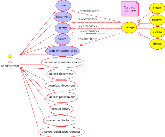
Fig4. Administrator Use case diagram
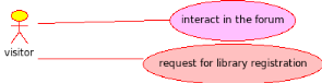
Fig5. Visitor use case
diagram
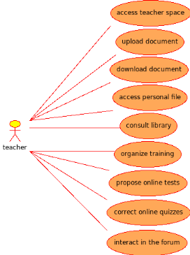
Fig6. Teacher use case
diagram
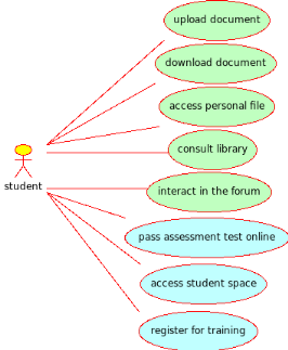
Fig7. Student use case
diagram: Student
2.4.4. Use case diagram:
Detailed textual description
2.4.4.1 Conduct of use case: Activity diagram
To describe the operational step-by-step
workflows; we shall
represent activity diagrams to show workflows of stepwise activities and
actions, they support choice, iteration and concurrency.
Here we will describe the conduct of some use cases.
Textual case scenario
"Authentication"
Tab4. Authentication
scenario
|
case
|
Authentication
|
|
Actor
|
All users expect simple visitors
|
|
Scenario
|
Succeeded
|
|
Pre-conditions
|
User already created
|
|
Actions
|
The system presents the home portal
The user selects connect
button
The system presents the login formulation
The user enters his
login and password
The system verifies and accepts or refuse the user's
identity
|
|
Post condition
|
The user is authenticated and is registered in the current
session
|
|
variants
|
The user enters an invalid login / password
The system asking
him again to authenticate.
|
![]()
Fig8. Activity diagram:
Authenticate
Textual case scenario "Consult
privileged space"
Tab5. Consult privileged
space scenario
|
case
|
Consult privileged space
|
|
Actor
|
All users expect simple visitors
|
|
Scenario
|
Succeeded
|
|
Pre-conditions
|
User already created
User belongs to concerned structure
|
|
Actions
|
The system presents the home portal
The user selects the menu
setting
The system presents the login formulation
The user enters his
login and password
The system verifies and accepts the user's
identity
Then the system creates a session and saves the user settings in
it
The system displays the page corresponding to the user profile
The
user accesses to all the features it has right
|
|
Post condition
|
The user is authenticated and is registered in the current
session
|
|
variants
|
The user has forgotten his login / password
The system asking
him again his authentication settings.
|
![]()
Fig9. Activity diagram:
Consult privileged space
Textual case scenario "Search
document"
Tab6. Search document
scenario
|
Case name
|
Search document
|
|
Actor
|
Administrator / teacher / student
|
|
Scenario
|
Succeeded
|
|
Preconditions
|
User authenticated
|
|
Actions
|
The user selects : <search document> button
The system
presents an interface of search types.
The user choose how to search the
document (by title - type - author...)
The system retrieves the
information
The user fill search keyword
The system displays all documents founded that appropriate with
user search
The user choose one of them and click on download link
The
system uploads the files from the server to the user local machine
The
system displays a message indicating the success of the file exportation.
|
|
Post condition
|
The system increments the number of downloaded .........
|
|
Variants
|
The user enters a wrong keyword
The system did not have any file appropriate to the
research
The system sends an error message
|
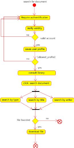
Fig10. Activity diagram:
Search document
Textual case scenario "register
for training"
Tab7. Register for training
scenario
|
Case
|
Register for training
|
|
Actor
|
Student
|
|
Scenario
|
Succeeded
|
|
Preconditions
|
Student authenticated
|
|
Actions
|
The
student selects : <Register for training> button
The system presents
all available training and all informations about each one
The system asks
the user to choose one
The user clicks on <ok> to select the chosen
one
The system verify compatibility between student and chosen training.
Student class=training class.
The deadline for registration does not exceed.
The number of places + 1 <= nb of limited places
The system
executes the command to creates the file contents in the database
The system adds the student to the list of registered for the
training.
The system update the list of registered for the training in the
administrator space.
The system displays a message indicating the success of
the registration.
|
|
Post condition
|
The system creates a new file in the database space
|
|
Variants
|
The student register for not allowed training / registration time
has expired / there are no more places.
The system sends an error message
|
![]()
Fig11. Activity diagram:
Register for training
2.4.4.2. Diagram of
sequences system
We'll now interest by the chronology of
interactions between objects and the system in general. So
we should present sequence diagrams.
Textual case scenario "Request
for registration"
|
Case name
|
Request for library registration
|
|
Actor
|
Visitor
|
|
Scenario
|
Succeeded
|
|
Preconditions
|
User have at least twenty earned points
|
|
Actions
|
The user selects : <request registration> button
The administrator system analyze visitor request
(he can accept or refuse according to many criteria)
if the
administrator accepts; system presents an interface for visitor to put these
informations
The user fill the registration form
The system add this
The system displays a message indicating
the success of the registration
The system create a new personal directory for this user
The administrator gives him privilege to consult library and
upload/download documents from.
|
|
Post condition
|
The system creates a new file in the database space
|
|
Variants
|
The user enters a wrong file / not permitted type
The system
sends an error message
|
Tab9. Request for registration scenario
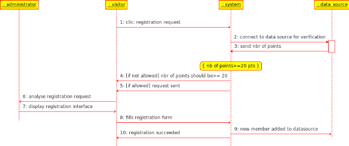
Fig12. Sequence diagram:
request for registration
Textual case scenario "Propose
online test"
Tab10. Propose online test
scenario
|
Case name
|
Propose online test
|
|
Actor
|
teacher
|
|
Scenario
|
Succeeded
|
|
Preconditions
|
User authenticated
|
|
Actions
|
The user clicks : <propose test> button
The system
presents a form to be fill by teacher
The teacher fills the form (indicating test information)
The system asks the user to give the file location
The user
clicks on <browse> and select the file path
The system retrieves the
path
The user clicks on import
The system downloads the files from the
local machine to the server
The system executes the command to creates the exam in the
database
The system displays a message indicating the success of the file
importation. The system create a new link for downloading the file in the
library space
The administrator announce concerned students by e-mail
|
|
Post condition
|
The system add the exam in the database space
|
|
Variants
|
The teacher enters a wrong file / not permitted type
There is no compatibility between concerned class and exam
date
The system sends an error message
|
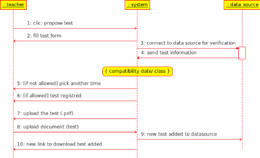
Fig13. Sequence diagram:
propose online test
2.7.2 Register for training
Student must be registered for training following these steps
and according to some constraints.
![]()
Fig14. Sequence diagram:
Register for training
2.8. Conclusion
In this chapter, we
identified the objectives of our system. These aims must
consider the problems of existing
solutions. This phase will help us for a fully
design of the application model that will be presented in the
next chapter, in order to discuss the design part and
discuss modeling of the needs expressed in this section.
Design of the solution
Chapter 3 Design
of the solution
3.1.
Introduction
Needs specification carried out in the preceding
chapter focuses only on the major processes of the project. It is necessary to
further study of the needs for a well project management: Design. It is
essential during the pre-study to ensure that the needs are expressed only in a
functional and not in terms of solutions.
So, after
completing the phase of analysis
and specification, we are now beginning
the design phase. This step is crucial
to the progress of the project and aims to detail
the tasks to be
undertaken and to prepare these grounds or
the implementation phase.
So, we present a general
concept of the application followed by detailed
diagram showing the database used. Then we detail the various application
modules as well as relations between the
modules through a package diagram and class
diagram. Finally, we
describe the kinetics of the application.
3.2. Architectural
Conception
3.2.1. Technical
architecture
Fig15. N-tier type
architecture
The review of our application
has demonstrated the need of a
§ System relational database
to store data.
§ Server application for logic
application.
§ Browser to access web pages.
So it requires the establishment of
three groups of functions: data storage, application
logic and presentation. These three parts
are independent from each other: we can change
the presentation without changing the application
logic.
Thus, the design of application logic
based on the data model and the design of the
presentation depends on the application logic; we choose to
implement layer-architecture.
Their main benefits are:
§ Application structure adapted
to the targeted deployment architecture
§
Modular application - Evolution facilitated the
application
§ Factorization of code with the
option to use a framework or generic components
(gain time and performance).
3.2.2 Logic application
architecture (three-layer)
Three-layer architecture principle is to separate
the achievement of the three parts previously seen (data
storage, application logic and presentation) to allow
the realization of
classic three-tier system architecture.One of the most important benefits of
this layer separation is that the generation
process becomes more optimized,
interfaces are non redundant which reduces
the response time.
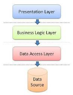
Fig16. Layers of
three-tier logic architecture
3.2.2.1 Presentation
layer
The presentation is the most immediately visible
to the user; it provides interactive access to the application. (You
could argue that user interaction layer might be more appropriate.)
3.2.2.2 Business logic
layer
§ Services
Layer
This layer combines the technical
treatments; non-functional requirements are
supported by the Framework Development.
§ Business
objects
these objects are the essential
work related to the
field of application. They require
treatment techniques, non-functional service
layer to manage security, transaction, competition.
3.2.2.3. Persistence layer
It consists of the database. Most often we add a layer that
makes the correspondence between objects and the database (DAO). This
layer is often used to cache objects retrieved from the database and thus
improves performance and security.
3.2.2.4 Advantages of three tier
architecture
Three-tier implementation have several advantages
including:
§ The logic is moved at the application server but is
programmed using the same technologies related to relational databases.
§ The ease of deployment; the application itself is
deployed on the server side (application server and database server). The
client requires only a minimal installation and configuration. Indeed, client
must only install a web browser to access application. This ease of deployment
will not only reduce the cost of deployment but also enable a steady evolution
of the system.
§ This development will facilitate the updating of the
application on the application server.
§ Improved security; using three-tier architecture of
database access is made only by the application server. This server is the
only one to know how to connect to the database. He does not share any
information that allows access to data, particularly the login and password of
the database. It is then possible to manage security at the application
server, for example by maintaining the list of users with their passwords and
their access rights to system functions.
§ We can even further improve security by establishing a
network architecture completely prohibiting access to the server database for
end users.
3.3. Detailed design
At this part we will start by presenting some
used design patterns; they are MVC, DAO and Session Façade.
3.3.1. Design pattern
A pattern describes a proven solution for a recurring design
problem, placing particular emphasis on the context and helps surrounding the
problem.
A design pattern is a general reusable solution to a
commonly occurring problem in
software design. It
is not a finished design that can be transformed directly into
code but
a description or template for how to solve a problem that can be used in many
different situations.
Object-oriented design
patterns typically show relationships and
interactions between
classes or
objects,
without specifying the final application classes or objects that are involved.
Many patterns imply
object-orientation or
more generally mutable state, and so may not be as applicable in
functional
programming languages, in which data is immutable or treated as
such.
3.3.1.1. MVC
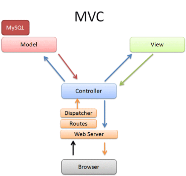
Fig17.
Model-view-controller
Participants & Responsibilities
It was originally applied to map the traditional input,
processing, and output tasks to the graphical user interaction model. Thus, it
is straightforward to map these concepts into the domain of multi-tier
enterprise applications.
§ Model - The model represents data
and business rules that govern access to and updates of this data. Often the
model serves as a software approximation to a real-world process, so simple
real-world modeling techniques apply when defining the model.
§ View -The view renders the contents
of a model. It accesses enterprise data through the model and specifies how
that data should be presented. It is the view's responsibility to maintain
consistency in its presentation when the model changes. This can be achieved by
using a push model, where the view registers itself with the model for change
notifications, or a pull model, where the view is responsible for calling the
model when it needs to retrieve the most current data.
§ Controller - The controller
translates interactions with the view into actions to be performed by the
model. In a stand-alone GUI client, user interactions could be button clicks or
menu selections, whereas in a Web application, they appear as GET and POST HTTP
requests. The actions performed by the model include activating business
processes or changing the state of the model. Based on the user interactions
and the outcome of the model actions, the controller responds by selecting an
appropriate view.
Strategies
Web-based clients such as browsers. Java Server
Pages (JSP) pages to render the view, Servlet as the controller, and
Enterprise JavaBeans (EJB) components as the model.
Centralized controller. Instead of having multiple
servlets as controllers, a main Servlet is used to make control more
manageable.
3.3.1.2. DAO
We use a Data Access Object (DAO) to abstract and encapsulate all
access to the data source. The DAO manages the connection with the data source
to obtain and store data.
The DAO implements the access mechanism required to work with the
data source. The data source could be a persistent store like an DBMS. The
business component that relies on the DAO uses the simpler interface exposed by
the DAO for its clients. The DAO completely hides the data source
implementation details from its clients. Because the interface exposed by the
DAO to clients does not change when the underlying data source implementation
changes, this pattern allows the DAO to adapt to different storage schemas
without affecting its clients or business components. Essentially, the DAO acts
as an adapter between the component and the data source.
Structure: Figure18 shows the class diagram representing
the relationships for the DAO pattern.
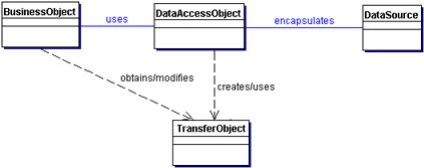
Fig18.Data Access Object
class diagram
Participants and Responsibilities
The following sequence diagram shows clearly the interaction
between the various participants in this pattern.
The Business Object represents the data client. It is the object
that requires access to the data source to obtain and store data. A Business
Object may be implemented as a session bean, entity bean, or some other Java
object, in addition to a servlet or helper bean that accesses the data
source.
The Data Access Object is the primary object of this pattern. The
Data Access Object abstracts the underlying data access implementation for the
Business Object to enable transparent access to the data source. The Business
Object also delegates data load and store operations to the Data Access
Object.
Data Source represents a data source implementation. A
data source could be a database such as an RDBMS, OODBMS, XML repository, and
so forth.
Transfer Object represents a Transfer Object used as a
data carrier. The Data Access Object may use a Transfer Object to return data
to the client. The Data Access Object may also receive the data from the client
in a Transfer Object to update the data in the data source.
3.3.1.3. Session Facade
We use a session bean as a facade to encapsulate the complexity
of interactions between the business objects participating in a workflow. The
Session Facade manages the business objects, and provides a uniform
coarse-grained service access layer to clients.
The Session Facade abstracts the underlying business object
interactions and provides a service layer that exposes only the required
interfaces. Thus, it hides from the client's view the complex interactions
between the participants. It manages the interactions between the business data
and business service objects that participate in the workflow, and it
encapsulates the business logic associated with the requirements. Thus, the
session bean (representing the Session Facade) manages the relationships
between business objects. The session bean also manages the life cycle of these
participants by creating, locating (looking up), modifying, and deleting them
as required by the workflow.
Use Cases and Session Facades
So, how can we identify the Session Facades through studying use
cases? Mapping every use case to a Session Facade will result in too many
Session Facades. This defeats the intention of having fewer coarse-grained
session beans. Instead, as we derive the Session Facades during our modeling,
it is essential to consolidate them into fewer numbers of session beans based
on some logical partitioning.
For example, for our application, we grouped the interactions
related to managing some units into a single facade. The use cases Create,
Change Information, View information, and so on all deal with the
coarse-grained entity object Account. Creating a session bean facade for each
use case is not recommended. Thus, the functions required to support these
related use cases could be grouped into a single Session Facade called
Management Session Facade.
Structure: Figure 19 shows the class diagram
representing the Session Facade pattern.
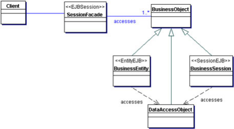
Fig19. Session facade class
diagram
Participants and Collaborations
The client of the Session Facade is who needs access to the
business service.
The SessionFacade is implemented as a session bean. It manages
the relationships between numerous BusinessObjects and provides a higher level
abstraction to the client.
The BusinessObject is a role object that facilitates applying
different strategies, such as session beans entity beans and a DAO (see the
next section, "Strategies"). A BusinessObject provides data and/or some service
in the class diagram. The SessionFacade interacts with multiple BusinessObject
instances to provide the service.
3.3.2 Data base conception
At this stage will present the various modules of
the system before exposing the class diagrams, then we
will finish by introducing the kinetics of the application.
Database details:
The user entity described by an id, name,
user surname and login/password for authentication. It also
contains other additional information as his privilege
id and e-mail.
The Internet user can view his privileged
space via his login and password, but he
must following the appropriate
role. Its timing (via calendar table)
and the address book (via Address Book
table).
It can also add or download documents
from the platform, ask questions, propose answers or
comments, organize or register for training/ online tests.
To
control and manage the application the administrator
thus may consult the database tables through web interfaces.
Table's presentation:
§ Person Table: Contains information of various
users of the system.
§ Document table: lists
all files exchanged between the different users.
§ Knowledge table: knowledge of professor
backup.
§ Person
knowledge table: contains the list of knowledge of
each teacher.
§ Privilege table: register the articles
of each user: administrator, user or teacher.
§ Question table: Saves the
questions posed and the user who asked each
question.
§ Answer table: The
response and the user responded to each question.
§ Training table: records all the
information necessary for training.
§ Calendar table:
contains the events created by users.
§ Address Book
table: contains lists of contacts for each Internet.
3.3.3 Packages
decomposition
To move to the design step, we
rely on the principles of the object-oriented approach;
we are moving from a functional structure
through the use case, to
a structure object through
classes and packages.
Given our application architecture and it's
large number of candidate classes; it was important to part
them into packages to better understand the overall
role of each part and facilitate code
maintenance.
To identify the packages, we rely on application
layers and independence criteria.
So we try to group classes that have
a strong correlation between them, which belong to
the same functional area: They must render similar
services to user. The package diagram of
our application as follow:
controller
models
Session beans
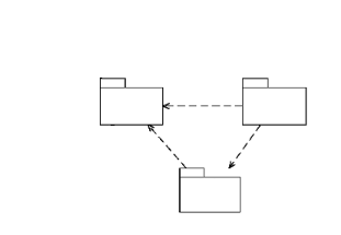
Fig20. Package
diagram
3.3.4 Class Diagram:
Static modeling is used to identify, refine
and complete classes of different packages seen in previous
section. It is to investigate the
relationships between them and invoke their attributes and
methods. The class diagram is the central point
in object-oriented development.
We will present the class diagram by
package.
3.3.4.1 Models package
Is the module
that contains all necessary class Entity that will be
traduced on tables in the database;
Each class entity represents only attributes (table columns),
class constructor, getter and setter for each attribute.
It contains seven classes that are: Person, Document, Privilege,
Question, Response, Knowledge and Training.
§ Person class has: id (person identifier),
login, password, name, first_name and e_mail attributes.
This class represents system users (our actors).
§ Privilege class has: id, user_role and
privilege attributes; this class will represent privilege table that contain
person_name and his associated privilege that can be: administrator, teacher,
student or visitor. Any user can have only one privilege and a privilege can be
associated to a group of person.
§ Question class: his attributes are
id_question, question, date_creation; it store all questions posed in the
forum. It is related with Person class to associate each question with his
creator; a question is posed by one person and any person can pose multi
questions.
Question class is also related to another class: Response
class.
§ Response class: it has id, response and
date_creation attributes; it is related with two classes Person and Question.
Thus a Response can't be created without question; a response is for only one
question, a question may have many responses. A response is associated for one
person but a person can provide many responses.
§ Training Class: his attributes are id,
training, delais_inscription, nbr_places and duree.
Represents all available trainings according to a specific date.
Any user who want to register for training should firstly be a student and
have some other criteria. So, a training can be followed by at least one
student and a student can follow many trainings.
§ Knowledge class: it has id and
knowledge_name attributes. It will represent knowledge table in the data base;
so it will stock each teacher's know ledges. Thus it is related to Person class
(we should mention here that we will catch only teacher knowledge) so when we
say knowledge person we mean that he has teacher privilege.
§ Document class: It has id, titre, auteur,
date_creation attributes. This class represents document Entity. A document can
be uploaded by only one person and a person can upload many documents, that's
why it is related to Person class.
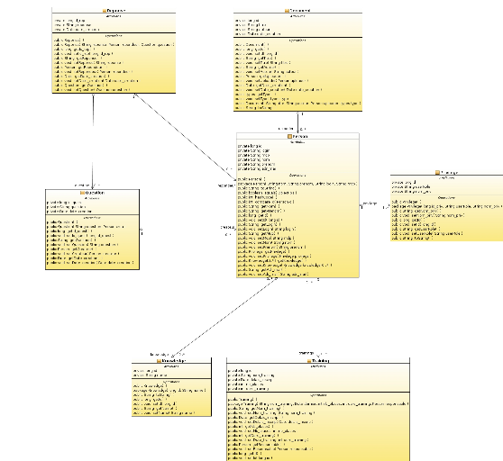
Fig21. Models
Package: class diagram
3.3.4.2 Session Beans
package
This package presents the data
persistence layer, it models the way of treatment
resource and interaction with the database.
The purpose of this package is to ensure the
flexible and easy data integrity guarantees and to adapt the
application with any data source.
It offers methods to update the data (create,
retrieve, update and delete). Here is a description
of some classes in this diagram:
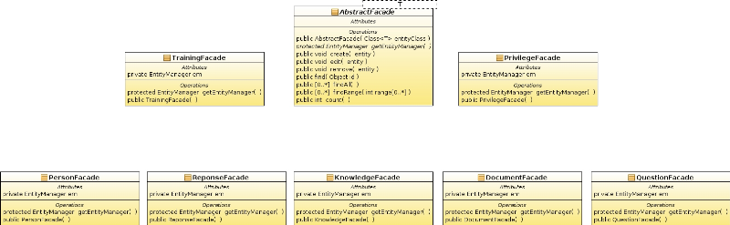
Fig22. Session beans
package: class diagram
This package contains seven classes:
TrainingFacade, PrivilegeFacade, Personfacade, ResponseFacade,
Knowledgefacade, DocumentFacade and QuestionFacade. Each one
appropriate with an entity class (classes of models package) and a generic
abstract class: AbstractFacade. Each one of these classes has only one
EntityManager attribute; it is associated with a persistence context that is a
set of entity instances in which for any persistent entity identity there is a
unique entity instance. Within the persistence context, the entity instances
and their lifecycle are managed. The EntityManager API is used to
create and remove persistent entity instances, to find entities by their
primary key, and to query over entities.
Each class of sessionbean package has getEntityManager method
that returns an EntityManager, a constructor and extends methods of
AbstractFacade class. They are create, edit, remove, find, findAll, findAll,
findRange and count that presents CRUD functionalities necessary to communicate
with data base.
3.3.4.3 Controller package
This layer supports the
management of interaction events between client interfaces
and persistence layer. It receives all user requests and
performs the appropriate actions.
This
module contains the following classes:
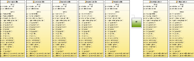
Fig23. Management process
package: Class Diagram
TrainingController, QuestionController,
ResponseController, DocumentController, PersonController, KnowledgeController
and knowledgeController.
Each one of them has two private attributes; DataModelItems
declared NULL and SelectedItemIndex. It has also his constructor and nineteen
other operation; getSelected() wich returns an element with the same type of
the Entity class related with, getFacade() returns an element with the type of
session beans package class related to, getPagination(): returns a
paginationHelper type, prepareList(), prepareView(), prepareCreate(),
prepareEdit(), create(), update (), destroy (), destroyAndReview (),
performDestroy (), updateCurrentItem (), getItems (), recreateModel (), next(),
previous () wich all return String Type. And two other methods that returns
SelectItem type; they are getItemsAvailableSelectMany() and
getItemsAvailableSelectone().
Each class of this package needs these methods to support
interactions between user interfaces and persistence layer.
the presentation layer (View) of our
application, which aims to
simplify the creation and editing interfaces; is
represented by some .xhtml pages that will be shown later.
Functional structure of the
application
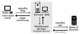
Fig25. Functional structure
of the application: user-side
3.3.5 Interaction Diagram
Interaction diagrams are models that describe how a group of
objects collaborate in some behavior typically a single use-case. The diagram
shows a number of example objects and messages that are passed between these
objects within the use-case.
I'll illustrate the approach with some examples of use-cases, but
firstly I will present interaction diagrams related with the application logic
architecture: they are Data Access Object and Session Façade diagrams.
They let us understand the conduct of each layer object very well.
Their textual description is mentioned in 3.3.1.2 and 3.3.1.1
parts.
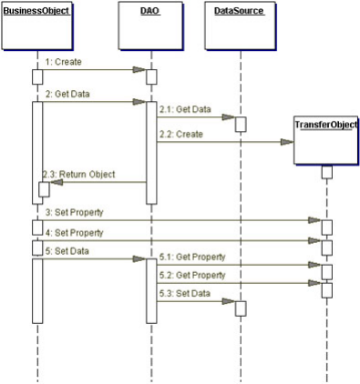
Fig24. Data Access Object
sequence diagram
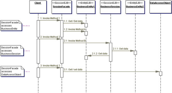
Fig25. Session Facade sequence diagram
Textual case scenario "upload document"
Tab8. Upload document
scenario
|
Case name
|
Upload documents
|
|
Actor
|
Administrator / teacher / student
|
|
Scenario
|
Succeeded
|
|
Preconditions
|
User authenticated
|
|
Actions
|
The user
click : <authenticate> button
The controller redirect him to
authentication page
The user fill his login and password
The PersonController catch them and send them to Personfacade
(DAO)
PersonFacade retrieve informations from Database which verify
user login/password:
If they are wrong: the user will be redirect to authentication
page again
If they are true: PersonFacade send them to PersonController.
If he is not a student; It will
redirect him to main page
If he is a student; he will be redirect
to student space.
The student click <exam registration>
Registration form will be displayed to him
The student fill his coordinates
The controller catch them and send them to PersonFacade
If the student is eligible to register; he will be added to
datasource
And a message indicates success of registration will be displayed
by controller in student interface.
If not; a message indicates the failure of registration will be
displayed
|
|
Post condition
|
The system creates a new registered student in the database
space
|
|
Variants
|
The user enters a wrong login / password
The system sends an
error message
There is no compatibility between student and exam classe
The system sends a failure registration message
|
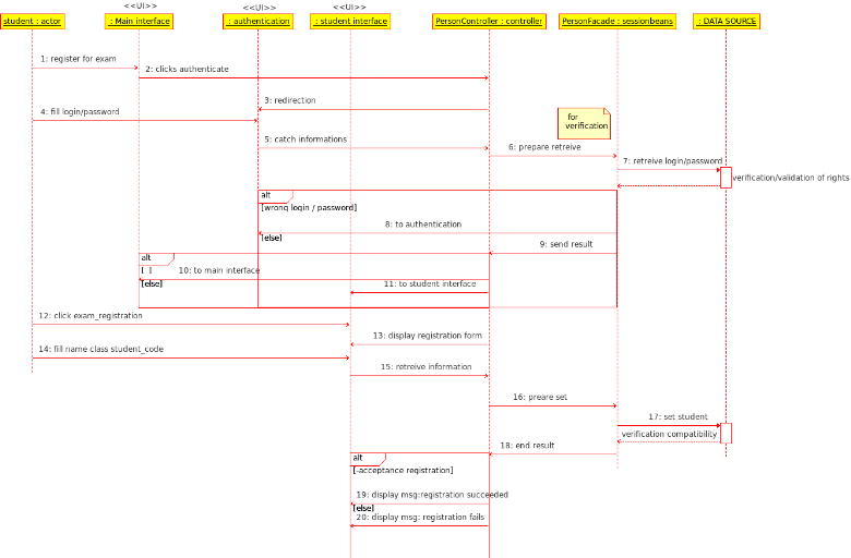
Fig26. Sequence diagram:
Upload document
Textual case scenario "Manage teacher skills
dashboard"
Tab8. Manage teacher skills dashboard
|
Case name
|
Manage teacher skills dashboard (set knowledge)
|
|
Actor
|
Administrator / teacher
|
|
Scenario
|
Succeeded
|
|
Preconditions
|
User authenticated
|
|
Actions
|
The teacher consult site (main interface)
Click <authenticate>
The controller redirects him to teacher space.
The teacher click update skills
The controller display message: upload your certification
The teacher clicks <upload document>
The controller asks the user to give the directories or files
location
The user clicks on <browse> and select the directory
path
The controller retrieves the path and send it to DAO
The user clicks
on import
The controller uploads the files from the local machine to the
server
The DAO set the document on the database (table document)
The DAO catch the document_id and send it to the Controller
The controller send a message: a teacher wants to update his
skills to admin space; it id is:( document_id)
The controller put download_link into admin space
The administrator click <download>
The administrator analyze the certification and click <update
skills>
The controlled executes the command to creates the file contents
in the database via DAO
The controller displays a message indicating the
success of update skills on teacher space..
|
|
Post condition
|
The system upload teacher skills
|
|
Variants
|
The user enters a wrong file / not permitted type
The system
sends an error message
|
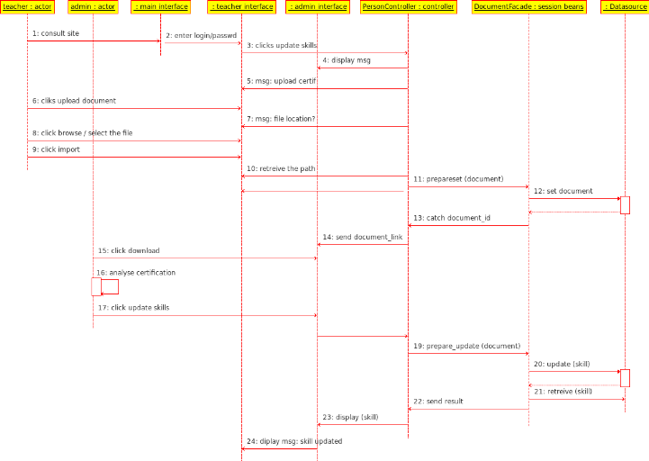
Fig27. Sequence diagram: Manage teacher skills
dashboard
3.4 Conclusion
Throughout this chapter,
we developed the design of our application to be flexible and
to provide easy passage to the next step; we first
presented the three-tier architecture. Secondly,
we described the architecture of our
application. Then we
have highlighted the database. Then we
presented the diagrams of classes. Finally we presented the kinetics of
diagram transitions diagram.
Implementation and validation
Chapter 4 Implementation
and validation
4.1
Introduction
The technical study is the adaptation phase of design
and the choice of technical architecture, describing and documenting the
function of each software unit.
In this chapter we will represent the
soul of the software development process and aims to
implement each of the modules described in
the previous chapter. We present in the first part our
application environment. Subsequently, we discuss interfaces that
present some functionalities of the system. Finally, we will
describe the tasks chronogram.
4.2 Working
Environment
4.2.1 Hardware Environment
We need at minimum
two machines for development and initial testing.
Subsequently, an Internet connection for each one will
suffice.. In all cases, we need a server
running, good
enough (multiprocessor, high-capacity memory alive) to support all
users connected and also a good internet connection.
For development we used a machine at medium
power: a laptop Pentium dual-core with
2MB of cache and 2GB of RAM.
4.2.2
Selection of programming language
We chose to develop our project with
Java for several reasons among which:
§ Its portability: It is independent of
the platform on which it runs (it only needs
to have a Java virtual machine).
§ Its disposal of a
library for handling different applications.
§ Our understanding of this language.
We have already said in the previous
chapter that we have to work with the 3-tier software
architecture; we have chosen J2EE as development language for these reasons:
4.2.3
J2EE Technologies implements 3-tier architecture
J2EE (Java 2 Enterprise Edition) is a platform
for application development based on
Java. J2EE architectures are used mainly for developing applications with a
complex architecture.
The development of such
application must take account of existing software
components and allows also possible future
developments (changing database, other types
of clients, changes in business logic, etc.).
J2EE
applications
are typically used in remote architectures (client
/ server). We will
study in what follows the architecture of distributed applications and J2EEcomponents.
4.2.3.1 J2EE let us benefit
from other technologies like JSF, JPA and
EJB
In our application, we need these
following technologies:
4.2.3.2 JSF: Java Server
Faces Technology
Java Server Faces technology establishes the standard for
building server-side user interfaces. With the contributions of the expert
group, the Java Server Faces APIs are being designed so that they can be
leveraged by tools that will make web application development even easier.
4.2.2.3 EJB: Enterprise
Java Beans
The EJB specification intends to provide a standard way to
implement the back-end 'business' code typically found in enterprise
applications. Enterprise JavaBeans were intended to handle such common concerns
as persistence, transactional integrity, and security in a standard way,
leaving programmers free to concentrate on the particular problem at hand.
Accordingly, the EJB specification details how an
application
server provides:
Transaction
processing, Integration with the
Persistence services
offered by the
Java Persistence
API (JPA),
Events using
Java Message
Service,
Deployment of
software
components in an application server, Exposing business methods as
Web Services...
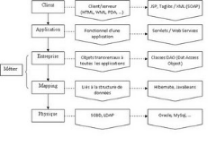
Fig27. Typical
example of a J2EE architecture
The architecture presented in the figure
above is a typical example consists of several
layers given by J2EE.
4.2.4 Software Environment
Throughout the development phase, we used
the following software environment:
§ Operating System: Ubuntu 10.04:
the best user friendly Linux desktop distribution
§
Tools Development: Net Beans 6.9
For dynamic web pages we need an application
server to compile and execute Java
classes representing the business of our application.
· Application Server
: Glass fish: new application
server, consistent specification J2EE 6,
integrated with Net Beans 6.9
·
Data Base Server: MySQL server to manage database.
· Design and Modeling with
UML: Umbrello: is a design tool
· Writing the
report and presentation: Open Office is free
and open source and free Text editor with correcting spelling
and grammar extensions.
4.2.4.1 Net Beans
Technical Reasons
Choosing an IDE (Integrated Development
Environment) is a critical step in the
project, This choice will gain
us in time and effort, therefore development
cost. We chose Net Beans development
environment for the application because it is Free,
developed by Sun: language founder of Java, its popularity
and flexibility is increasing. It integrates Glass Fish Server.
It is a complete development platform; because
its environmental baseline includes all these following
functions:
§ It is free and includes all
the features of a modern IDE (syntax
highlighting, multi-language projects, refactoring, editor graphic interfaces
and web pages, etc.).
§ configuration and management GUI,
§ support for different programming languages,
§ Treatment of the source
code (editing, navigation, formatting, inspection ..)
§
access and management of databases, Web servers, shared
resources: it includes a query editor,
a manager of integrated databases ...
§
We can also add libraries as its main
library mail.jar. For sending mail.
4.2.4.2 Choice of
MySQL
The database requirement is motivated not
only by the need to serve documents created
dynamically but also access to
daily information constantly changing, with a
simple and unified interface, so we have chosen because
it is very easy to change and manage. It supports API (Application
Programming Interface) clients with many programming
languages ??(Java, C, etc.) which can easily write
client programs that need access to data
in a MySQL database.
4.3 Deployment Diagram
This diagram shows the physical organization
of the application design, it specifies the
components to
our application. In our case we need an
application server to deploy our application above;
a database server to store the database tables, as well
as the customer requires a browser to
access web pages.
ESPRIT must have sufficiently
powerful application servers to be able to handle the
traffic of a large number of Internet users.
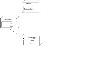
Fig28. Deployment
diagram
4.4 Implementation
The GUI
(graphical user interface) is the most crucial
part in a web application. It contributes to
the construction of the first user impression on the
system. Indeed, it is a criterion
that can adds the difference between two web
applications although they have the same functionality.
Thus, we tried to provide attractive interfaces that should give
the main application features.
The first interface that will be displayed to the
user of our system is the main interface; it contain forum,
request for registration and connexion space. If he already
has an account, he has to provide its parameters,
user name / password so
can access his privileged space. A page will
display to him that contains all his permitted features so can choose any
other fonctionnality he needs; so he will be automatically redirect to another
web page. If not he can only interact in the forum.
-I will present the application and all its interfaces in test
validity-.
4.5 Timing
diagram
To be managed in a quality, a project must follow different
phases during which, each point should define a step: task, to detect
non-conformances at the earliest and adapt to new stresses due to unforeseen
contingencies initially. Therefore, it is essential to control the time
allocated to each task.
This project was conducted
from November 21, 2010 to April 9,
2011. We first started by a
phase of literature on information related
to our application field and a thorough review of the
existing order to understand the
needs and begin the work. Then, after
clearing and understood what is asked, we were able
to meet the functional and non functional
requirements. Then we started the design
phase and implemented the requested module after
passing through technology documentation
we will use.
How do we devise the work?
What was the followed process to obtain a system that must be
functional?
Tasks that compose our project from documentation to realization
are:
Task 1: Preparatory phase (documentation):
the
preparation of documents having a relationship with the topic of project and
indicating its organizational conditions.
Task 2 : establishment
of requirements specification:
Redaction of tender specification
Task 3:
Feasibility study:
we talk about the technical feasibility of
the project.
This phase is triggered by reception of the specification:
functional and non fictional requirements.
Task 4: The study of
scenarios: Analysis
the feasibility study leads to consider
several scenarios (the « cases study » to be implemented by our
system).
This step aims to identify and document each feature that must
provide our software and create specification documents, which will form the
basis of the specifications trend. It is in this stage that the conception of
the software graphical interface will be created.
Task 5 :
Detailed design: Conception
Design
work is to determine the theoretical technical
solutions that will satisfy the specifications, that is to
apply the expectations of the user. The result of
the work is application
diagrams such as class diagrams and interaction
diagram.
Task 6:Development of application: Realization:
Construction
The construction is the main activity, which occupies more
than half of the total development time. During this step
we write the software source
code.
The various modules of
the software are programmed one by one, then collected.
And quotation of goals achieved compared to those original.
Task 7: Test of application validity
Tests
are performed to verify the functioning of the whole
(integration test); conducts many tests to detect a
maximum of bugs - errors in programming is
advised.
Task 8: application delivery, reporting and
presentation
When the application is running and once we have tested its
operation, we can deliver it with the explanatory report which was written
chapter by chapter simultaneously with all other tasks (every step achieved it
must be explained in the report).
To organize and to carry out the
project, we established a detailed diagram of the
various tasks that constitute our project.
The Gantt
diagram is a tool used in project management for viewing various tasks that
comprise the project according to time. It is a graphical representation of the
progress of the project, modeling and planning tasks.
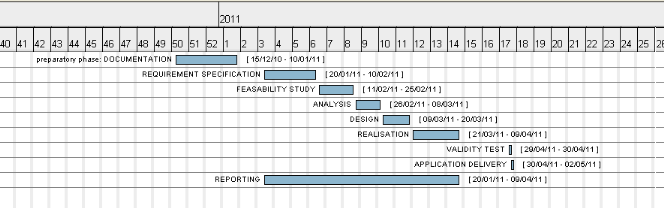
Fig32. Gantt diagram
(sequencing tasks / time)
4.6 Conclusion
In this chapter, we presented the
development; hardware and software
environment of which ends this
project. We have also presented an overview of
the final
application through some printed displays and the timing of
the tasks performed during this work. Also,
the study of the existing system has allowed us to be
familiar with the field study and understand the working
procedures of the current
system.
Thus, we discovered deficiencies, and existing
anomalies from the validity tests and make appropriate
suggestions, which allows us to design improvements to
our system to meet identified needs.
General conclusion
This
project was a good opportunity to get out of
the theoretical framework and apply
knowledge acquired during university studies for a real
working environment that allowed me to initiate in
professional field.
In technical terms, this work made
??me discover new concepts and technologies related
to Java and multilayer architectures, and it
was a very good opportunity to understand
the various UML diagrams and the necessity of each
one.
The profit is essential to learn how to
use existing technology and to integrate into our
application respecting the temporal constraints that
are not always easy to follow.
The time
constraint thus evoked prevented
us from adding more features to our
application we have estimated technically
feasible, among which we mention the possibility of
integrating our application chat
module, add a space for sharing media
such as audio, videos, and optimize code to
reduce the response time.
In this report
we have developed four chapters. In
the first, we presented the general framework of
our application and the various solutions
adopted vis-à-vis the issue. In the second
chapter we studied the
functional and nonfunctional and the specification
requirements. The design part was analyzed in the
third chapter. We ended the report
by the realization containing the main part of
the application interfaces.
Netography
www.developpez.com
www.wikipedia.org
www.uml.free.fr
www.commentcamarche.net
www.oracle.com
| 

