IV.7.3 Insertion des donnees
1er Etape : consiste à insérer
ou à choisir le type et les caractéristiques du fluide utiliser
fig. (IV.1).
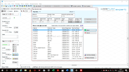
Figure IV.1 Choix du type de fluide
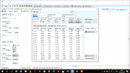
2er Etape : consiste à insérer
ou à choisir le matériau, le diamètre et les
caractéristiques de la conduite utiliser fig. (IV.2).
Figure
IV.1 Choix du matériau des conduites
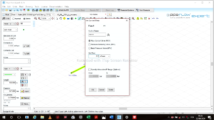
3er Etape : consiste a choisir la vanne et a
insérer les différentes caractéristiques de la vanne fig.
(IV.3).
Figure
IV.3 Choix de la vanne
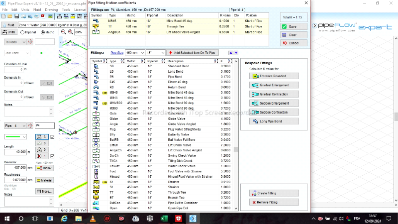
4er Etape : consiste à insérer
ou à choisir les coudes (45° et 90°), la crépine et le
clapet anti-retour ainsi que leurs les différentes les
caractéristiques fig. (IV.4).
Figure
IV.1 Choix des coudes, crépine et clapet
anti-retour
5er Etape : consiste à insérer
ou à choisir la pompe ainsi que les différentes les
caractéristiques (la courbe du réseau et la courbe la pompe, la
vitesse de rotation, le débit, la hauteur manométrique, le
rendement, le NPSH, ...) fig. (IV.5).
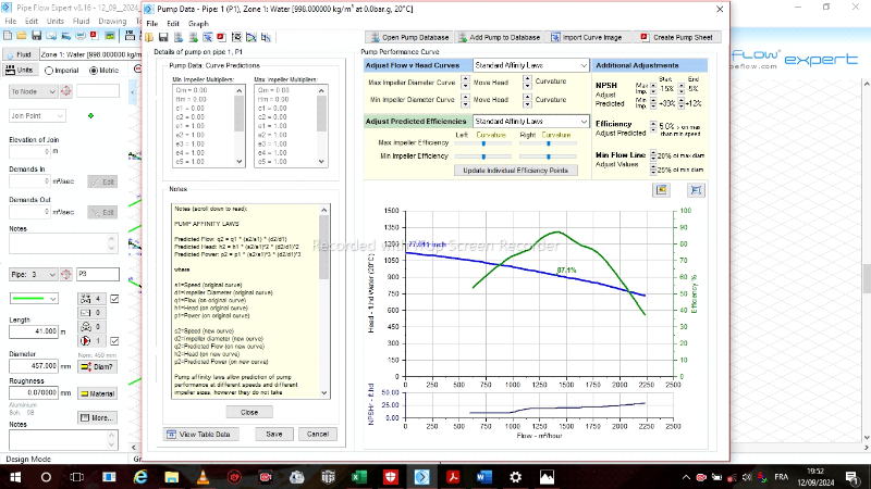
Figure IV.1
Choix du type de pompe
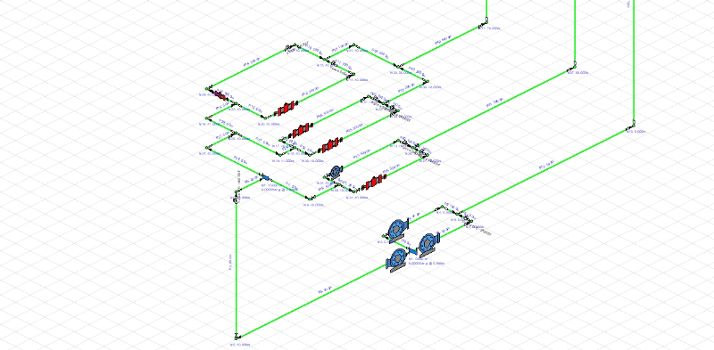
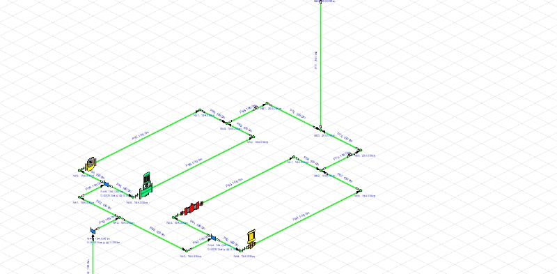
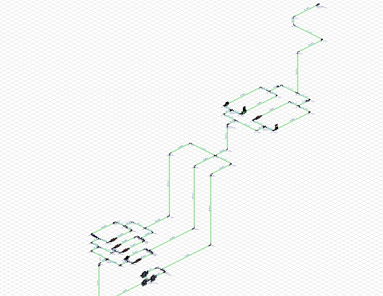
IV.7.4 Conception du système
Ce système est composé de 13 pompes,
reparti comme suite :
· Niveau 505 : 3 pompes HPL en bleu ;
· Niveau 465 : 1 pompe HPL(bleu) et 5 pompes
Flowserve (rouge) ;
· Niveau 396 : 1 pompe Flowserse(rouge), 1 pompe
ACEC(jaune), 1 pompe Diebolde(jaune) et pompe et 1 Griffo
· Niveau 505 au 465
· Niveau 369
· Tout le Système
IV.7.5 Apres simulation
Après simulation nous obtenons les résultats
suivants
Tableau IV.1.
Résultat après simulation pour les fluides
|
FLUIDS
|
|
Zone
|
Fluid Name
|
Chemical Formula
|
Temperature°C
|
Pressure bar.g
|
Density kg/m
|
Centistokes
|
Centipoise
|
Vapour Pressure bar.a
|
State
|
|
1
|
Water
|
H2O
|
20
|
0
|
998
|
1
|
1,002
|
0,024
|
Liquid
|
Nous avons utilisé l'eau à une temperature de
20 , une pression de 0 bar et une densité de 998
Kg/m3
Tableau IV.2.
Résultat après simulation pour les matériaux des
conduites
|
Pipe Materials
|
|
Pipe Id
|
Pipe Name
|
Nominal Size
|
Material
|
Schedule
|
Roughness
|
Inner Diameter
|
Wall Thickness
|
Outer Diameter
|
Length
|
Weight
|
Internal Volume
|
Surface Area
|
|
|
|
|
|
Class
|
mm
|
mm
|
mm
|
mm
|
m
|
kg (full length)
|
m
|
m²
|
|
1
|
P1
|
450 mm
|
Aluminium
|
Sch. 5S
|
0,07
|
457
|
1,651
|
460,302
|
30
|
8,34
|
4,921
|
43,382
|
|
2
|
P2
|
450 mm
|
Aluminium
|
Sch. 5S
|
0,07
|
457
|
1,651
|
460,302
|
100
|
27,8
|
16,403
|
144,608
|
|
3
|
P3
|
450 mm
|
Aluminium
|
Sch. 5S
|
0,07
|
457
|
1,651
|
460,302
|
41
|
11,398
|
6,725
|
59,289
|
|
|
|
|
|
|
|
|
|
|
|
|
|
|
4
|
P4
|
450 mm
|
Aluminium
|
Sch. 5S
|
0,07
|
457
|
1,651
|
460,302
|
40
|
11,12
|
6,561
|
57,843
|
|
5
|
P5
|
450 mm
|
Aluminium
|
Sch. 5S
|
0,07
|
457
|
1,651
|
460,302
|
80
|
22,24
|
13,122
|
115,687
|
|
6
|
P6
|
450 mm
|
Aluminium
|
Sch. 5S
|
0,07
|
457
|
1,651
|
460,302
|
20
|
5,56
|
3,281
|
28,922
|
|
7
|
P7
|
450 mm
|
Aluminium
|
Sch. 5S
|
0,07
|
457
|
1,651
|
460,302
|
5
|
1,39
|
0,82
|
7,23
|
|
8
|
P8
|
450 mm
|
Aluminium
|
Sch. 5S
|
0,07
|
457
|
1,651
|
460,302
|
100
|
27,8
|
16,403
|
144,608
|
|
9
|
P9
|
450 mm
|
Aluminium
|
Sch. 5S
|
0,07
|
457
|
1,651
|
460,302
|
20
|
5,56
|
3,281
|
28,922
|
|
10
|
P10
|
450 mm
|
Aluminium
|
Sch. 5S
|
0,07
|
457
|
1,651
|
460,302
|
30
|
8,34
|
4,921
|
43,382
|
|
11
|
P11
|
450 mm
|
Aluminium
|
Sch. 5S
|
0,07
|
457
|
1,651
|
460,302
|
200
|
55,6
|
32,806
|
289,216
|
|
12
|
P12
|
450 mm
|
Aluminium
|
Sch. 5S
|
0,07
|
457
|
1,651
|
460,302
|
300
|
83,4
|
49,209
|
433,824
|
|
13
|
P13
|
450 mm
|
Aluminium
|
Sch. 5S
|
0,07
|
457
|
1,651
|
460,302
|
5
|
1,39
|
0,82
|
7,23
|
|
14
|
P14
|
450 mm
|
Aluminium
|
Sch. 5S
|
0,07
|
457
|
1,651
|
460,302
|
100
|
27,8
|
16,403
|
144,608
|
|
15
|
P15
|
450 mm
|
Aluminium
|
Sch. 5S
|
0,07
|
457
|
1,651
|
460,302
|
100
|
27,8
|
16,403
|
144,608
|
|
16
|
P16
|
450 mm
|
Aluminium
|
Sch. 5S
|
0,07
|
457
|
1,651
|
460,302
|
300
|
83,4
|
49,209
|
433,824
|
|
17
|
P17
|
450 mm
|
Aluminium
|
Sch. 5S
|
0,07
|
457
|
1,651
|
460,302
|
100
|
27,8
|
16,403
|
144,608
|
|
18
|
P18
|
450 mm
|
Aluminium
|
Sch. 5S
|
0,07
|
457
|
1,651
|
460,302
|
30
|
8,34
|
4,921
|
43,382
|
|
19
|
P19
|
450 mm
|
Aluminium
|
Sch. 5S
|
0,07
|
457
|
1,651
|
460,302
|
5
|
1,39
|
0,82
|
7,23
|
|
20
|
P20
|
450 mm
|
Aluminium
|
Sch. 5S
|
0,07
|
457
|
1,651
|
460,302
|
100
|
27,8
|
16,403
|
144,608
|
|
21
|
P21
|
450 mm
|
Aluminium
|
Sch. 5S
|
0,07
|
457
|
1,651
|
460,302
|
30
|
8,34
|
4,921
|
43,382
|
|
22
|
P22
|
450 mm
|
Aluminium
|
Sch. 5S
|
0,07
|
457
|
1,651
|
460,302
|
100
|
27,8
|
16,403
|
144,608
|
|
23
|
P23
|
450 mm
|
Aluminium
|
Sch. 5S
|
0,07
|
457
|
1,651
|
460,302
|
5
|
1,39
|
0,82
|
7,23
|
|
24
|
P24
|
450 mm
|
Aluminium
|
Sch. 5S
|
0,07
|
457
|
1,651
|
460,302
|
30
|
8,34
|
4,921
|
43,382
|
|
25
|
P25
|
450 mm
|
Aluminium
|
Sch. 5S
|
0,07
|
457
|
1,651
|
460,302
|
300
|
83,4
|
49,209
|
433,824
|
|
26
|
P26
|
450 mm
|
Aluminium
|
Sch. 5S
|
0,07
|
457
|
1,651
|
460,302
|
5
|
1,39
|
0,82
|
7,23
|
|
27
|
P27
|
450 mm
|
Aluminium
|
Sch. 5S
|
0,07
|
457
|
1,651
|
460,302
|
5
|
1,39
|
0,82
|
7,23
|
|
28
|
P28
|
450 mm
|
Aluminium
|
Sch. 5S
|
0,07
|
457
|
1,651
|
460,302
|
20
|
5,56
|
3,281
|
28,922
|
|
29
|
P29
|
450 mm
|
Aluminium
|
Sch. 5S
|
0,07
|
457
|
1,651
|
460,302
|
150
|
41,7
|
24,604
|
216,912
|
|
30
|
P30
|
450 mm
|
Aluminium
|
Sch. 5S
|
0,07
|
457
|
1,651
|
460,302
|
150
|
41,7
|
24,604
|
216,912
|
|
31
|
P31
|
450 mm
|
Aluminium
|
Sch. 5S
|
0,07
|
457
|
1,651
|
460,302
|
5
|
1,39
|
0,82
|
7,23
|
|
32
|
P32
|
450 mm
|
Aluminium
|
Sch. 5S
|
0,07
|
457
|
1,651
|
460,302
|
5
|
1,39
|
0,82
|
7,23
|
|
33
|
P33
|
450 mm
|
Aluminium
|
Sch. 5S
|
0,07
|
457
|
1,651
|
460,302
|
200
|
55,6
|
32,806
|
289,216
|
|
34
|
P34
|
450 mm
|
Aluminium
|
Sch. 5S
|
0,07
|
457
|
1,651
|
460,302
|
400
|
111,2
|
65,612
|
578,433
|
|
35
|
P35
|
450 mm
|
Aluminium
|
Sch. 5S
|
0,07
|
457
|
1,651
|
460,302
|
100
|
27,8
|
16,403
|
144,608
|
|
36
|
P36
|
450 mm
|
Aluminium
|
Sch. 5S
|
0,07
|
457
|
1,651
|
460,302
|
500
|
139
|
82,015
|
723,041
|
|
37
|
P37
|
450 mm
|
Aluminium
|
Sch. 5S
|
0,07
|
457
|
1,651
|
460,302
|
500
|
139
|
82,015
|
723,041
|
|
38
|
P38
|
450 mm
|
Aluminium
|
Sch. 5S
|
0,07
|
457
|
1,651
|
460,302
|
300
|
83,4
|
49,209
|
433,824
|
|
39
|
P39
|
450 mm
|
Aluminium
|
Sch. 5S
|
0,07
|
457
|
1,651
|
460,302
|
5
|
1,39
|
0,82
|
7,23
|
|
40
|
P40
|
450 mm
|
Aluminium
|
Sch. 5S
|
0,07
|
457
|
1,651
|
460,302
|
300
|
83,4
|
49,209
|
433,824
|
|
41
|
P41
|
450 mm
|
Aluminium
|
Sch. 5S
|
0,07
|
457
|
1,651
|
460,302
|
500
|
139
|
82,015
|
723,041
|
|
42
|
P42
|
450 mm
|
Aluminium
|
Sch. 5S
|
0,07
|
457
|
1,651
|
460,302
|
600
|
166,8
|
98,418
|
867,649
|
|
43
|
P43
|
450 mm
|
Aluminium
|
Sch. 5S
|
0,07
|
457
|
1,651
|
460,302
|
150
|
41,7
|
24,604
|
216,912
|
|
44
|
P44
|
450 mm
|
Aluminium
|
Sch. 5S
|
0,07
|
457
|
1,651
|
460,302
|
100
|
27,8
|
16,403
|
144,608
|
|
45
|
P45
|
450 mm
|
Aluminium
|
Sch. 5S
|
0,07
|
457
|
1,651
|
460,302
|
155
|
43,09
|
25,425
|
224,143
|
|
46
|
P46
|
450 mm
|
Aluminium
|
Sch. 5S
|
0,07
|
457
|
1,651
|
460,302
|
100
|
27,8
|
16,403
|
144,608
|
|
47
|
P47
|
450 mm
|
Aluminium
|
Sch. 5S
|
0,07
|
457
|
1,651
|
460,302
|
150
|
41,7
|
24,604
|
216,912
|
|
48
|
P48
|
450 mm
|
Aluminium
|
Sch. 5S
|
0,07
|
457
|
1,651
|
460,302
|
100
|
27,8
|
16,403
|
144,608
|
|
49
|
P49
|
450 mm
|
Aluminium
|
Sch. 5S
|
0,07
|
457
|
1,651
|
460,302
|
200
|
55,6
|
32,806
|
289,216
|
|
50
|
P50
|
450 mm
|
Aluminium
|
Sch. 5S
|
0,07
|
457
|
1,651
|
460,302
|
100
|
27,8
|
16,403
|
144,608
|
|
51
|
P51
|
450 mm
|
Aluminium
|
Sch. 5S
|
0,07
|
457
|
1,651
|
460,302
|
200
|
55,6
|
32,806
|
289,216
|
|
52
|
P52
|
450 mm
|
Aluminium
|
Sch. 5S
|
0,07
|
457
|
1,651
|
460,302
|
100
|
27,8
|
16,403
|
144,608
|
|
53
|
P53
|
450 mm
|
Aluminium
|
Sch. 5S
|
0,07
|
457
|
1,651
|
460,302
|
100
|
27,8
|
16,403
|
144,608
|
|
54
|
P54
|
450 mm
|
Aluminium
|
Sch. 5S
|
0,07
|
457
|
1,651
|
460,302
|
100
|
27,8
|
16,403
|
144,608
|
|
55
|
P55
|
450 mm
|
Aluminium
|
Sch. 5S
|
0,07
|
457
|
1,651
|
460,302
|
100
|
27,8
|
16,403
|
144,608
|
|
56
|
P56
|
450 mm
|
Aluminium
|
Sch. 5S
|
0,07
|
457
|
1,651
|
460,302
|
100
|
27,8
|
16,403
|
144,608
|
|
57
|
P57
|
450 mm
|
Aluminium
|
Sch. 5S
|
0,033
|
457
|
1,651
|
460,302
|
100
|
27,8
|
16,403
|
144,608
|
|
58
|
P58
|
450 mm
|
Aluminium
|
Sch. 5S
|
0,07
|
457
|
1,651
|
460,302
|
100
|
27,8
|
16,403
|
144,608
|
|
59
|
P59
|
450 mm
|
Aluminium
|
Sch. 5S
|
0,07
|
457
|
1,651
|
460,302
|
100
|
27,8
|
16,403
|
144,608
|
|
60
|
P60
|
450 mm
|
Aluminium
|
Sch. 5S
|
0,07
|
457
|
1,651
|
460,302
|
100
|
27,8
|
16,403
|
144,608
|
|
61
|
P61
|
450 mm
|
Aluminium
|
Sch. 5S
|
0,07
|
457
|
1,651
|
460,302
|
100
|
27,8
|
16,403
|
144,608
|
|
62
|
P62
|
450 mm
|
Aluminium
|
Sch. 5S
|
0,07
|
457
|
1,651
|
460,302
|
100
|
27,8
|
16,403
|
144,608
|
|
63
|
P63
|
450 mm
|
Aluminium
|
Sch. 5S
|
0,07
|
457
|
1,651
|
460,302
|
100
|
27,8
|
16,403
|
144,608
|
|
64
|
P64
|
450 mm
|
Aluminium
|
Sch. 5S
|
0,07
|
457
|
1,651
|
460,302
|
100
|
27,8
|
16,403
|
144,608
|
|
65
|
P65
|
450 mm
|
Aluminium
|
Sch. 5S
|
0,07
|
457
|
1,651
|
460,302
|
100
|
27,8
|
16,403
|
144,608
|
|
66
|
P66
|
450 mm
|
Aluminium
|
Sch. 5S
|
0,07
|
457
|
1,651
|
460,302
|
100
|
27,8
|
16,403
|
144,608
|
|
67
|
P67
|
450 mm
|
Aluminium
|
Sch. 5S
|
0,07
|
457
|
1,651
|
460,302
|
100
|
27,8
|
16,403
|
144,608
|
|
68
|
P68
|
450 mm
|
Aluminium
|
Sch. 5S
|
0,07
|
457
|
1,651
|
460,302
|
100
|
27,8
|
16,403
|
144,608
|
|
69
|
P69
|
450 mm
|
Aluminium
|
Sch. 5S
|
0,07
|
457
|
1,651
|
460,302
|
100
|
27,8
|
16,403
|
144,608
|
|
70
|
P70
|
450 mm
|
Aluminium
|
Sch. 5S
|
0,07
|
457
|
1,651
|
460,302
|
100
|
27,8
|
16,403
|
144,608
|
|
71
|
P71
|
450 mm
|
Aluminium
|
Sch. 5S
|
0,07
|
457
|
1,651
|
460,302
|
200
|
55,6
|
32,806
|
289,216
|
|
72
|
P72
|
450 mm
|
Aluminium
|
Sch. 5S
|
0,07
|
457
|
1,651
|
460,302
|
100
|
27,8
|
16,403
|
144,608
|
|
73
|
P73
|
450 mm
|
Aluminium
|
Sch. 5S
|
0,07
|
457
|
1,651
|
460,302
|
200
|
55,6
|
32,806
|
289,216
|
|
74
|
P74
|
450 mm
|
Aluminium
|
Sch. 5S
|
0,07
|
457
|
1,651
|
460,302
|
100
|
27,8
|
16,403
|
144,608
|
|
75
|
P75
|
450 mm
|
Aluminium
|
Sch. 5S
|
0,07
|
457
|
1,651
|
460,302
|
100
|
27,8
|
16,403
|
144,608
|
|
76
|
P76
|
450 mm
|
Aluminium
|
Sch. 5S
|
0,07
|
457
|
1,651
|
460,302
|
100
|
27,8
|
16,403
|
144,608
|
|
77
|
P77
|
450 mm
|
Aluminium
|
Sch. 5S
|
0,07
|
457
|
1,651
|
460,302
|
100
|
27,8
|
16,403
|
144,608
|
Pour les matériels des tuyaux nous avons utilisé
77 conduites en aluminum de differentes longueurs de diametres interieur de 457
mm soit 18pouces et 460 de diametres exterieur et nous pouvons voir pour chaque
conduite la surface ainsi que le volume.
Tableau IV.2.
Résultat après simulation pour les accessoires des conduites
(Tuyauteries)
|
Pipe Fittings
|
|
Pipe Id
|
Pipe
|
Fitting Position
|
Description
|
Imperial Size
|
Metric Size
|
Database Ref
|
K Value
|
Quantity
|
K Total
|
Entry K Total
|
|
1
|
P1
|
Start of Pipe
|
Mitre Bend 45 deg.
|
18"
|
450 mm
|
MB45
|
0,19
|
1
|
0,19
|
|
|
1
|
P1
|
Start of Pipe
|
Through Tee
|
18"
|
450 mm
|
TT
|
0,28
|
1
|
0,28
|
|
|
1
|
P1
|
Start of Pipe
|
Lift Check Valve Angled
|
18"
|
450 mm
|
AngleCh
|
0,66
|
1
|
0,66
|
|
|
1
|
P1
|
End of Pipe
|
Mitre Bend 90 deg.
|
18"
|
450 mm
|
MB90
|
0,72
|
1
|
0,72
|
1,13
|
|
2
|
P2
|
Start of Pipe
|
Mitre Bend 45 deg.
|
18"
|
450 mm
|
MB45
|
0,19
|
1
|
0,19
|
0,19
|
|
3
|
P3
|
Start of Pipe
|
Mitre Bend 45 deg.
|
18"
|
450 mm
|
MB45
|
0,19
|
1
|
0,19
|
|
|
3
|
P3
|
Start of Pipe
|
Through Tee
|
18"
|
450 mm
|
TT
|
0,28
|
1
|
0,28
|
|
|
3
|
P3
|
Start of Pipe
|
Lift Check Valve Angled
|
18"
|
450 mm
|
AngleCh
|
0,66
|
1
|
0,66
|
|
|
3
|
P3
|
End of Pipe
|
Mitre Bend 90 deg.
|
18"
|
450 mm
|
MB90
|
0,72
|
1
|
0,72
|
1,13
|
|
4
|
P4
|
Start of Pipe
|
Mitre Bend 45 deg.
|
18"
|
450 mm
|
MB45
|
0,19
|
1
|
0,19
|
|
|
4
|
P4
|
Start of Pipe
|
Through Tee
|
18"
|
450 mm
|
TT
|
0,28
|
1
|
0,28
|
|
|
4
|
P4
|
Start of Pipe
|
Lift Check Valve Angled
|
18"
|
450 mm
|
AngleCh
|
0,66
|
1
|
0,66
|
1,13
|
|
5
|
P5
|
Start of Pipe
|
Mitre Bend 45 deg.
|
18"
|
450 mm
|
MB45
|
0,19
|
1
|
0,19
|
|
|
5
|
P5
|
Start of Pipe
|
Mitre Bend 90 deg.
|
18"
|
450 mm
|
MB90
|
0,72
|
1
|
0,72
|
|
|
5
|
P5
|
Start of Pipe
|
Lift Check Valve Angled
|
18"
|
450 mm
|
AngleCh
|
0,66
|
1
|
0,66
|
|
|
5
|
P5
|
Start of Pipe
|
Through Tee
|
18"
|
450 mm
|
TT
|
0,28
|
1
|
0,28
|
1,85
|
|
6
|
P6
|
Start of Pipe
|
Mitre Bend 45 deg.
|
18"
|
450 mm
|
MB45
|
0,19
|
1
|
0,19
|
|
|
6
|
P6
|
Start of Pipe
|
Mitre Bend 90 deg.
|
18"
|
450 mm
|
MB90
|
0,72
|
1
|
0,72
|
0,91
|
|
7
|
P7
|
Start of Pipe
|
Mitre Bend 45 deg.
|
18"
|
450 mm
|
MB45
|
0,19
|
1
|
0,19
|
0,19
|
|
8
|
P8
|
Start of Pipe
|
Mitre Bend 45 deg.
|
18"
|
450 mm
|
MB45
|
0,19
|
1
|
0,19
|
0,19
|
|
9
|
P9
|
Start of Pipe
|
Mitre Bend 45 deg.
|
18"
|
450 mm
|
MB45
|
0,19
|
1
|
0,19
|
0,19
|
|
10
|
P10
|
Start of Pipe
|
Mitre Bend 45 deg.
|
18"
|
450 mm
|
MB45
|
0,19
|
1
|
0,19
|
|
|
10
|
P10
|
End of Pipe
|
Mitre Bend 45 deg.
|
18"
|
450 mm
|
MB45
|
0,19
|
1
|
0,19
|
0,19
|
|
11
|
P11
|
Start of Pipe
|
Mitre Bend 45 deg.
|
18"
|
450 mm
|
MB45
|
0,19
|
1
|
0,19
|
0,19
|
|
12
|
P12
|
Start of Pipe
|
Mitre Bend 45 deg.
|
18"
|
450 mm
|
MB45
|
0,19
|
1
|
0,19
|
|
|
12
|
P12
|
Start of Pipe
|
Through Tee
|
18"
|
450 mm
|
TT
|
0,28
|
1
|
0,28
|
|
|
12
|
P12
|
End of Pipe
|
Lift Check Valve Angled
|
18"
|
450 mm
|
AngleCh
|
0,66
|
1
|
0,66
|
0,47
|
|
13
|
P13
|
Start of Pipe
|
Mitre Bend 45 deg.
|
18"
|
450 mm
|
MB45
|
0,19
|
1
|
0,19
|
0,19
|
|
14
|
P14
|
Start of Pipe
|
Mitre Bend 45 deg.
|
18"
|
450 mm
|
MB45
|
0,19
|
1
|
0,19
|
0,19
|
|
15
|
P15
|
Start of Pipe
|
Mitre Bend 45 deg.
|
18"
|
450 mm
|
MB45
|
0,19
|
1
|
0,19
|
0,19
|
|
16
|
P16
|
Start of Pipe
|
Mitre Bend 45 deg.
|
18"
|
450 mm
|
MB45
|
0,19
|
1
|
0,19
|
|
|
16
|
P16
|
Start of Pipe
|
Through Tee
|
18"
|
450 mm
|
TT
|
0,28
|
1
|
0,28
|
|
|
16
|
P16
|
Start of Pipe
|
Lift Check Valve Angled
|
18"
|
450 mm
|
AngleCh
|
0,66
|
1
|
0,66
|
1,13
|
|
17
|
P17
|
Start of Pipe
|
Mitre Bend 45 deg.
|
18"
|
450 mm
|
MB45
|
0,19
|
1
|
0,19
|
0,19
|
|
18
|
P18
|
Start of Pipe
|
Mitre Bend 45 deg.
|
18"
|
450 mm
|
MB45
|
0,19
|
1
|
0,19
|
|
|
18
|
P18
|
Start of Pipe
|
Through Tee
|
18"
|
450 mm
|
TT
|
0,28
|
1
|
0,28
|
|
|
18
|
P18
|
Start of Pipe
|
Lift Check Valve Angled
|
18"
|
450 mm
|
AngleCh
|
0,66
|
1
|
0,66
|
1,13
|
|
19
|
P19
|
Start of Pipe
|
Mitre Bend 45 deg.
|
18"
|
450 mm
|
MB45
|
0,19
|
1
|
0,19
|
0,19
|
|
20
|
P20
|
Start of Pipe
|
Mitre Bend 45 deg.
|
18"
|
450 mm
|
MB45
|
0,19
|
1
|
0,19
|
0,19
|
|
21
|
P21
|
Start of Pipe
|
Mitre Bend 45 deg.
|
18"
|
450 mm
|
MB45
|
0,19
|
1
|
0,19
|
0,19
|
|
22
|
P22
|
Start of Pipe
|
Mitre Bend 45 deg.
|
18"
|
450 mm
|
MB45
|
0,19
|
1
|
0,19
|
0,19
|
|
23
|
P23
|
Start of Pipe
|
Mitre Bend 45 deg.
|
18"
|
450 mm
|
MB45
|
0,19
|
1
|
0,19
|
0,19
|
|
24
|
P24
|
Start of Pipe
|
Mitre Bend 45 deg.
|
18"
|
450 mm
|
MB45
|
0,19
|
1
|
0,19
|
0,19
|
|
25
|
P25
|
Start of Pipe
|
Mitre Bend 45 deg.
|
18"
|
450 mm
|
MB45
|
0,19
|
1
|
0,19
|
|
|
25
|
P25
|
Start of Pipe
|
Through Tee
|
18"
|
450 mm
|
TT
|
0,28
|
1
|
0,28
|
|
|
25
|
P25
|
End of Pipe
|
Lift Check Valve Angled
|
18"
|
450 mm
|
AngleCh
|
0,66
|
1
|
0,66
|
0,47
|
|
26
|
P26
|
Start of Pipe
|
Mitre Bend 45 deg.
|
18"
|
450 mm
|
MB45
|
0,19
|
1
|
0,19
|
0,19
|
|
27
|
P27
|
Start of Pipe
|
Mitre Bend 45 deg.
|
18"
|
450 mm
|
MB45
|
0,19
|
1
|
0,19
|
|
|
27
|
P27
|
Start of Pipe
|
Through Tee
|
18"
|
450 mm
|
TT
|
0,28
|
1
|
0,28
|
|
|
27
|
P27
|
End of Pipe
|
Ball Valve Full Bore
|
18"
|
450 mm
|
BallFB
|
0,04
|
1
|
0,04
|
0,47
|
|
28
|
P28
|
Start of Pipe
|
Mitre Bend 45 deg.
|
18"
|
450 mm
|
MB45
|
0,19
|
1
|
0,19
|
0,19
|
|
29
|
P29
|
Start of Pipe
|
Mitre Bend 45 deg.
|
18"
|
450 mm
|
MB45
|
0,19
|
1
|
0,19
|
0,19
|
|
30
|
P30
|
Start of Pipe
|
Mitre Bend 45 deg.
|
18"
|
450 mm
|
MB45
|
0,19
|
1
|
0,19
|
0,19
|
|
31
|
P31
|
Start of Pipe
|
Mitre Bend 45 deg.
|
18"
|
450 mm
|
MB45
|
0,19
|
1
|
0,19
|
0,19
|
|
32
|
P32
|
Start of Pipe
|
Mitre Bend 45 deg.
|
18"
|
450 mm
|
MB45
|
0,19
|
1
|
0,19
|
0,19
|
|
33
|
P33
|
Start of Pipe
|
Mitre Bend 45 deg.
|
18"
|
450 mm
|
MB45
|
0,19
|
1
|
0,19
|
0,19
|
|
34
|
P34
|
Start of Pipe
|
Mitre Bend 45 deg.
|
18"
|
450 mm
|
MB45
|
0,19
|
1
|
0,19
|
0,19
|
|
35
|
P35
|
Start of Pipe
|
Mitre Bend 45 deg.
|
18"
|
450 mm
|
MB45
|
0,19
|
1
|
0,19
|
0,19
|
|
36
|
P36
|
Start of Pipe
|
Mitre Bend 45 deg.
|
18"
|
450 mm
|
MB45
|
0,19
|
1
|
0,19
|
|
|
36
|
P36
|
Start of Pipe
|
Through Tee
|
18"
|
450 mm
|
TT
|
0,28
|
1
|
0,28
|
|
|
36
|
P36
|
Start of Pipe
|
Lift Check Valve Angled
|
18"
|
450 mm
|
AngleCh
|
0,66
|
1
|
0,66
|
1,13
|
|
37
|
P37
|
Start of Pipe
|
Mitre Bend 45 deg.
|
18"
|
450 mm
|
MB45
|
0,19
|
1
|
0,19
|
|
|
37
|
P37
|
Start of Pipe
|
Through Tee
|
18"
|
450 mm
|
TT
|
0,28
|
1
|
0,28
|
|
|
37
|
P37
|
Start of Pipe
|
Lift Check Valve Angled
|
18"
|
450 mm
|
AngleCh
|
0,66
|
1
|
0,66
|
1,13
|
|
38
|
P38
|
Start of Pipe
|
Mitre Bend 45 deg.
|
18"
|
450 mm
|
MB45
|
0,19
|
1
|
0,19
|
|
|
38
|
P38
|
Start of Pipe
|
Through Tee
|
18"
|
450 mm
|
TT
|
0,28
|
1
|
0,28
|
|
|
38
|
P38
|
End of Pipe
|
Lift Check Valve Angled
|
18"
|
450 mm
|
AngleCh
|
0,66
|
1
|
0,66
|
0,47
|
|
39
|
P39
|
Start of Pipe
|
Mitre Bend 45 deg.
|
18"
|
450 mm
|
MB45
|
0,19
|
1
|
0,19
|
0,19
|
|
40
|
P40
|
Start of Pipe
|
Mitre Bend 45 deg.
|
18"
|
450 mm
|
MB45
|
0,19
|
1
|
0,19
|
0,19
|
|
41
|
P41
|
Start of Pipe
|
Mitre Bend 45 deg.
|
18"
|
450 mm
|
MB45
|
0,19
|
1
|
0,19
|
|
|
41
|
P41
|
Start of Pipe
|
Hinged Foot Valve with Strainer
|
18"
|
450 mm
|
Hinged
|
0,9
|
1
|
0,9
|
|
|
41
|
P41
|
End of Pipe
|
Through Tee
|
18"
|
450 mm
|
TT
|
0,28
|
1
|
0,28
|
1,09
|
|
42
|
P42
|
Start of Pipe
|
Mitre Bend 45 deg.
|
18"
|
450 mm
|
MB45
|
0,19
|
1
|
0,19
|
|
|
42
|
P42
|
Start of Pipe
|
Through Tee
|
18"
|
450 mm
|
TT
|
0,28
|
1
|
0,28
|
|
|
42
|
P42
|
End of Pipe
|
Hinged Foot Valve with Strainer
|
18"
|
450 mm
|
Hinged
|
0,9
|
1
|
0,9
|
0,47
|
|
43
|
P43
|
Start of Pipe
|
Mitre Bend 45 deg.
|
18"
|
450 mm
|
MB45
|
0,19
|
1
|
0,19
|
0,19
|
|
44
|
P44
|
Start of Pipe
|
Mitre Bend 45 deg.
|
18"
|
450 mm
|
MB45
|
0,19
|
1
|
0,19
|
0,19
|
|
45
|
P45
|
Start of Pipe
|
Mitre Bend 45 deg.
|
18"
|
450 mm
|
MB45
|
0,19
|
1
|
0,19
|
|
|
45
|
P45
|
End of Pipe
|
Mitre Bend 45 deg.
|
18"
|
450 mm
|
MB45
|
0,19
|
1
|
0,19
|
0,19
|
|
46
|
P46
|
Start of Pipe
|
Mitre Bend 45 deg.
|
18"
|
450 mm
|
MB45
|
0,19
|
1
|
0,19
|
0,19
|
|
47
|
P47
|
Start of Pipe
|
Mitre Bend 45 deg.
|
18"
|
450 mm
|
MB45
|
0,19
|
1
|
0,19
|
|
|
47
|
P47
|
End of Pipe
|
Through Tee
|
18"
|
450 mm
|
TT
|
0,28
|
1
|
0,28
|
0,19
|
|
48
|
P48
|
Start of Pipe
|
Mitre Bend 45 deg.
|
18"
|
450 mm
|
MB45
|
0,19
|
2
|
0,38
|
|
|
48
|
P48
|
Start of Pipe
|
Standard Bend
|
18"
|
450 mm
|
SB
|
0,36
|
1
|
0,36
|
|
|
48
|
P48
|
Start of Pipe
|
Through Tee
|
18"
|
450 mm
|
TT
|
0,28
|
1
|
0,28
|
|
|
48
|
P48
|
End of Pipe
|
Mitre Bend 90 deg.
|
18"
|
450 mm
|
MB90
|
0,72
|
2
|
1,44
|
1,02
|
|
49
|
P49
|
Start of Pipe
|
Mitre Bend 45 deg.
|
18"
|
450 mm
|
MB45
|
0,19
|
1
|
0,19
|
0,19
|
|
50
|
P50
|
Start of Pipe
|
Mitre Bend 45 deg.
|
18"
|
450 mm
|
MB45
|
0,19
|
1
|
0,19
|
0,19
|
|
51
|
P51
|
Start of Pipe
|
Mitre Bend 45 deg.
|
18"
|
450 mm
|
MB45
|
0,19
|
1
|
0,19
|
0,19
|
|
52
|
P52
|
Start of Pipe
|
Mitre Bend 45 deg.
|
18"
|
450 mm
|
MB45
|
0,19
|
1
|
0,19
|
0,19
|
|
53
|
P53
|
Start of Pipe
|
Mitre Bend 45 deg.
|
18"
|
450 mm
|
MB45
|
0,19
|
1
|
0,19
|
0,19
|
|
54
|
P54
|
Start of Pipe
|
Mitre Bend 45 deg.
|
18"
|
450 mm
|
MB45
|
0,19
|
1
|
0,19
|
0,19
|
|
55
|
P55
|
Start of Pipe
|
Mitre Bend 45 deg.
|
18"
|
450 mm
|
MB45
|
0,19
|
1
|
0,19
|
0,19
|
|
56
|
P56
|
Start of Pipe
|
Mitre Bend 45 deg.
|
18"
|
450 mm
|
MB45
|
0,19
|
1
|
0,19
|
0,19
|
|
57
|
P57
|
Start of Pipe
|
Mitre Bend 45 deg.
|
18"
|
450 mm
|
MB45
|
0,19
|
1
|
0,19
|
|
|
57
|
P57
|
Start of Pipe
|
Through Tee
|
18"
|
450 mm
|
TT
|
0,28
|
1
|
0,28
|
|
|
57
|
P57
|
Start of Pipe
|
Lift Check Valve Angled
|
18"
|
450 mm
|
AngleCh
|
0,66
|
1
|
0,66
|
1,13
|
|
58
|
P58
|
Start of Pipe
|
Mitre Bend 45 deg.
|
18"
|
450 mm
|
MB45
|
0,19
|
1
|
0,19
|
|
|
58
|
P58
|
Start of Pipe
|
Through Tee
|
18"
|
450 mm
|
TT
|
0,28
|
1
|
0,28
|
|
|
58
|
P58
|
Start of Pipe
|
Lift Check Valve Angled
|
18"
|
450 mm
|
AngleCh
|
0,66
|
1
|
0,66
|
1,13
|
|
59
|
P59
|
Start of Pipe
|
Mitre Bend 45 deg.
|
18"
|
450 mm
|
MB45
|
0,19
|
1
|
0,19
|
0,19
|
|
60
|
P60
|
Start of Pipe
|
Mitre Bend 45 deg.
|
18"
|
450 mm
|
MB45
|
0,19
|
1
|
0,19
|
0,19
|
|
61
|
P61
|
Start of Pipe
|
Mitre Bend 45 deg.
|
18"
|
450 mm
|
MB45
|
0,19
|
1
|
0,19
|
0,19
|
|
62
|
P62
|
Start of Pipe
|
Mitre Bend 45 deg.
|
18"
|
450 mm
|
MB45
|
0,19
|
1
|
0,19
|
0,19
|
|
63
|
P63
|
Start of Pipe
|
Mitre Bend 45 deg.
|
18"
|
450 mm
|
MB45
|
0,19
|
1
|
0,19
|
|
|
63
|
P63
|
Start of Pipe
|
Through Tee
|
18"
|
450 mm
|
TT
|
0,28
|
1
|
0,28
|
|
|
63
|
P63
|
Start of Pipe
|
Lift Check Valve Angled
|
18"
|
450 mm
|
AngleCh
|
0,66
|
1
|
0,66
|
1,13
|
|
64
|
P64
|
Start of Pipe
|
Mitre Bend 45 deg.
|
18"
|
450 mm
|
MB45
|
0,19
|
1
|
0,19
|
|
|
64
|
P64
|
Start of Pipe
|
Through Tee
|
18"
|
450 mm
|
TT
|
0,28
|
1
|
0,28
|
|
|
64
|
P64
|
Start of Pipe
|
Lift Check Valve Angled
|
18"
|
450 mm
|
AngleCh
|
0,66
|
1
|
0,66
|
1,13
|
|
65
|
P65
|
Start of Pipe
|
Mitre Bend 45 deg.
|
18"
|
450 mm
|
MB45
|
0,19
|
1
|
0,19
|
0,19
|
|
66
|
P66
|
Start of Pipe
|
Mitre Bend 45 deg.
|
18"
|
450 mm
|
MB45
|
0,19
|
1
|
0,19
|
|
|
66
|
P66
|
End of Pipe
|
Mitre Bend 90 deg.
|
18"
|
450 mm
|
MMMB90
|
1,5
|
1
|
1,5
|
0,19
|
|
67
|
P67
|
Start of Pipe
|
Mitre Bend 90 deg.
|
18"
|
450 mm
|
MMMB90
|
1,5
|
2
|
3
|
|
|
67
|
P67
|
End of Pipe
|
Mitre Bend 45 deg.
|
18"
|
450 mm
|
MB45
|
0,19
|
1
|
0,19
|
3
|
|
68
|
P68
|
Start of Pipe
|
Mitre Bend 45 deg.
|
18"
|
450 mm
|
MB45
|
0,19
|
1
|
0,19
|
0,19
|
|
69
|
P69
|
Start of Pipe
|
Mitre Bend 45 deg.
|
18"
|
450 mm
|
MB45
|
0,19
|
1
|
0,19
|
|
|
69
|
P69
|
Start of Pipe
|
Mitre Bend 90 deg.
|
18"
|
450 mm
|
MMMB90
|
1,5
|
3
|
4,5
|
4,69
|
|
70
|
P70
|
Start of Pipe
|
Mitre Bend 90 deg.
|
18"
|
450 mm
|
MMMB90
|
1,5
|
1
|
1,5
|
|
|
70
|
P70
|
End of Pipe
|
Mitre Bend 45 deg.
|
18"
|
450 mm
|
MB45
|
0,19
|
1
|
0,19
|
1,5
|
|
71
|
P71
|
Start of Pipe
|
Mitre Bend 45 deg.
|
18"
|
450 mm
|
MB45
|
0,19
|
1
|
0,19
|
|
|
71
|
P71
|
End of Pipe
|
Mitre Bend 90 deg.
|
18"
|
450 mm
|
MMMB90
|
1,5
|
1
|
1,5
|
0,19
|
|
72
|
P72
|
Start of Pipe
|
Mitre Bend 45 deg.
|
18"
|
450 mm
|
MB45
|
0,19
|
1
|
0,19
|
|
|
72
|
P72
|
End of Pipe
|
Strainer
|
18"
|
450 mm
|
St
|
0,0077
|
1
|
0,0077
|
0,19
|
|
73
|
P73
|
Start of Pipe
|
Mitre Bend 45 deg.
|
18"
|
450 mm
|
MB45
|
0,19
|
1
|
0,19
|
|
|
73
|
P73
|
Start of Pipe
|
Mitre Bend 90 deg.
|
18"
|
450 mm
|
MMMB90
|
1,5
|
1
|
1,5
|
1,69
|
|
74
|
P74
|
Start of Pipe
|
Mitre Bend 45 deg.
|
18"
|
450 mm
|
MB45
|
0,19
|
1
|
0,19
|
|
|
74
|
P74
|
Start of Pipe
|
Mitre Bend 90 deg.
|
18"
|
450 mm
|
MMMB90
|
1,5
|
1
|
1,5
|
1,69
|
|
75
|
P75
|
Start of Pipe
|
Mitre Bend 45 deg.
|
18"
|
450 mm
|
MB45
|
0,19
|
1
|
0,19
|
0,19
|
|
76
|
P76
|
Start of Pipe
|
Mitre Bend 45 deg.
|
18"
|
450 mm
|
MB45
|
0,19
|
1
|
0,19
|
0,19
|
|
77
|
P77
|
Start of Pipe
|
Mitre Bend 45 deg.
|
18"
|
450 mm
|
MB45
|
0,19
|
1
|
0,19
|
|
|
77
|
P77
|
Start of Pipe
|
Strainer
|
18"
|
450 mm
|
St
|
0,0077
|
1
|
0,0077
|
|
|
77
|
P77
|
End of Pipe
|
Mitre Bend 90 deg.
|
18"
|
450 mm
|
MMMB90
|
1,5
|
1
|
1,5
|
|
Nous pouvons voir sur ce tableau les différents
accessoires ou raccords de conduites pour les 77 pipes. Le nombres, la valeur
de K pour les accessoires placer au début et à la fin de la
conduite. coudes de 45° ou 90° degrés, les clapets et les
crépines. Ainsi avons :
· Les coudes de 90° et 45° : 94 ;
· Les clapets anti-retours : 13 ;
· Les crépines : 22
Tableau IV.3.
Résultat après simulation pour les vannes régulatrices du
débit
|
FCV Results
|
|
Fluid Zone
|
Material
|
Inner Diameter
mm
|
FCV Name
|
FCV Mass Flow
kg/sec
|
FCV Vol Flow
m/sec
|
FCV Loss
m.hd
|
Calculated Cv
|
Calculated Kv
|
|
Water (20°C at 0,0bar.g, density 998,000000 kg/m)
|
450 mm Aluminium Sch. 5S
|
457
|
Vanne 505 - 465 REF
|
1,1775
|
0,0012
|
1,498
|
12,82
|
11,09
|
|
Water (20°C at 0,0bar.g, density 998,000000 kg/m)
|
450 mm Aluminium Sch. 5S
|
457
|
Vanne 505 - 345 REF
|
1,1775
|
0,0012
|
156,533
|
1,25
|
1,09
|
|
Water (20°C at 0,0bar.g, density 998,000000 kg/m)
|
450 mm Aluminium Sch. 5S
|
457
|
Vanne 505 REF
|
1,1775
|
0,0012
|
200,041
|
1,11
|
0,96
|
|
Water (20°C at 0,0bar.g, density 998,000000 kg/m)
|
450 mm Aluminium Sch. 5S
|
457
|
Vanne 505 REF
|
1,1775
|
0,0012
|
200,041
|
1,11
|
0,96
|
|
Water (20°C at 0,0bar.g, density 998,000000 kg/m)
|
450 mm Aluminium Sch. 5S
|
457
|
Vanne 505 REF
|
1,1775
|
0,0012
|
200,041
|
1,11
|
0,96
|
|
Water (20°C at 0,0bar.g, density 998,000000 kg/m)
|
450 mm Aluminium Sch. 5S
|
457
|
Vanne 505 REF
|
1,1775
|
0,0012
|
200,041
|
1,11
|
0,96
|
|
Water (20°C at 0,0bar.g, density 998,000000 kg/m)
|
450 mm Aluminium Sch. 5S
|
457
|
Vanne 505 REF
|
1,1775
|
0,0012
|
200,043
|
1,11
|
0,96
|
|
Water (20°C at 0,0bar.g, density 998,000000 kg/m)
|
450 mm Aluminium Sch. 5S
|
457
|
Vanne 505 REF
|
1,1775
|
0,0012
|
200,043
|
1,11
|
0,96
|
|
Water (20°C at 0,0bar.g, density 998,000000
kg/m)
|
450 mm Aluminium Sch. 5S
|
457
|
|
1,1775
|
0,0012
|
72,491
|
1,84
|
1,59
|
|
Water (20°C at 0,0bar.g, density 998,000000
kg/m)
|
450 mm Aluminium Sch. 5S
|
457
|
|
1,1775
|
0,0012
|
72,491
|
1,84
|
1,59
|
Nous avons les resultats pour les 10 vannes régulations
du débit, un débit massique de 1,117 Kg/sec et un débit
volumetrique de 0,0012m3/sec . Nous avons differentes pertes de
changes à differents endroits ou nous avons placer les vannes . Nous
pouvons aussi constater la chute de pression pour le fluite et les
débits à partir du coefficient CV ainsi que le coefficient KV qui
indique le volume d'eau en m3/s.
Tableau IV.2.
Résultat après simulation pour les différentes
Pompes
|
Pump Results
|
|
Pipe Id
|
Pipe Name
|
Pump Name
|
Speed
|
Pref. Op From
|
Pref. Op To
|
Flow In/Out
|
Velocity
|
Suction Pressure
|
Discharge Pressure
|
Pump Head (+)
|
Pump NPSHr
|
Pump NPSHa
|
Pump Efficiency
|
Pump Power
|
|
|
|
rpm
|
m/sec
|
m/sec
|
m/sec
|
m/sec
|
bar.g
|
bar.g
|
m.hd
|
m.hd (absolute)
|
m.hd (absolute)
|
Percentage
|
Kilowatts
|
|
1
|
P1
|
Pump HLP 1
|
1180
|
1,5759
|
1,9699
|
0,0012
|
0,007
|
0
|
33,4162
|
341,433
|
0,036
|
10,108
|
3,96
|
99,62
|
|
3
|
P3
|
Pump HLP 3
|
Set Flow Rate
|
|
|
0,1278
|
0,779
|
-0,0143
|
18,1136
|
185,223
|
Not known
|
9,962
|
Not known
|
Not Known
|
|
4
|
P4
|
Pump HLP 2
|
1475
|
0,5903
|
1,0962
|
0,0012
|
0,007
|
0
|
4,3551
|
44,498
|
0,033
|
10,108
|
46,14
|
1,1138
|
|
12
|
P12
|
Pump Flowserve
|
1180
|
1,5759
|
1,9699
|
0,0012
|
0,007
|
0,2936
|
33,7098
|
341,434
|
0,036
|
13,108
|
3,77
|
104,6546
|
|
14
|
P14
|
Pump Flowserve
|
1180
|
1,5759
|
1,9699
|
0,0012
|
0,007
|
0,2936
|
33,7098
|
341,434
|
0,036
|
13,108
|
3,77
|
104,6546
|
|
25
|
P25
|
Pump Flowserve
|
1180
|
1,5759
|
1,9699
|
0,0012
|
0,007
|
0,2936
|
33,7098
|
341,434
|
0,036
|
13,108
|
3,77
|
104,6546
|
|
36
|
P36
|
Pump flowserve
|
1180
|
1,5759
|
1,9699
|
0,0012
|
0,007
|
0,2936
|
33,7098
|
341,434
|
0,036
|
13,108
|
3,77
|
104,6546
|
|
37
|
P37
|
Pump HPL
|
1180
|
1,5759
|
1,9699
|
0,0012
|
0,007
|
0,2936
|
33,7098
|
341,434
|
0,036
|
13,108
|
3,77
|
104,6546
|
|
38
|
P38
|
Pump
|
1180
|
1,5759
|
1,9699
|
0,0012
|
0,007
|
0,2936
|
33,7098
|
341,434
|
0,036
|
13,108
|
3,77
|
104,6546
|
|
57
|
P57
|
Pump griffo
|
1180
|
1,5759
|
1,9699
|
0,0006
|
0,004
|
0
|
33,4219
|
341,492
|
0,018
|
10,108
|
3,75
|
52,5413
|
|
58
|
P58
|
Pump Diebold
|
1180
|
1,5759
|
1,9699
|
0,0006
|
0,004
|
0
|
33,4219
|
341,491
|
0,018
|
10,108
|
3,75
|
52,5421
|
|
63
|
P63
|
Pump Flowseve
|
1180
|
1,5759
|
1,9699
|
0,0006
|
0,004
|
0
|
33,4219
|
341,491
|
0,018
|
10,108
|
3,75
|
52,5539
|
|
64
|
P64
|
Ppump acec
|
1180
|
1,5759
|
1,9699
|
0,0006
|
0,004
|
0
|
33,4219
|
341,492
|
0,018
|
10,108
|
3,75
|
52,5403
|
Nous avons observé
· La vitesse de rotation des pompes de 1180   (tours par minutes), (tours par minutes),
· Le meilleur rendement varie entre 1.5757 m3/s
à 1.9699 m3/s,
· Le débit à l'entrée et à la
sortie des pompes est répertorier dans le tableau ci-haut à la
colonne Flow In/Out;
· La vitesse est de répertorier dans le tableau
ci-haut à la colonneVelocityen m/sec ;
· La pression à l'aspiration étant de 0.2936
bar et au refoulement 33.4219 bar ;
· La hauteur manométrique est
répertoriée dans la colonne Pump Head
(+) ;
· Les NPSHr et le NPSHa repertorier dans les colonnes
Pump NPSHr et Pump NPSHapour les
différentes pompes ;
· Les différents rendements des pompes nous le
retrouvons dans la colonne Pump Efficiency ;
· La puissance a de l'arbre requise au point de
fonctionnement.
|
|