5.5. System design
The following step consist on the technical modelling of
therequirements. In engineering discipline model is crucial and is used to
describe the shapes or actions of any construction that must be built. The
benefits of the model are the requirement clarification and performance of a
construction. The main objectives of design model is to support system
complexity and reduce the error in the software development processes.(Ali,
Shukur, & Idris, 2007)
5.5.1. System
Architecture
In the study the client-server architecture is the base system
architecture, since it attempts to balance the processing between client
devices and one or more server devices. In the client-server architecture, the
client is responsible for the presentation logic, whereas the server is
responsible for the data access logic and data storage.(Dennis et al., 2012) We
will use thick or fat client approach wherethe client contains most of the
application logic and the server contains the data repository so the proposed
system will be a stand-alone application.

Figure 3.2: System architecture
5.5.2. The process
modelling
Unified Modeling Language `(UML) is increasingly used as the
standard for software modelling and design. The most recent version (UML 2.0
under OMG 2004) includes 13 distinct modelling notations ranging from
high-level use case diagrams, which illustrate the scenario of the interactions
between actors and major business tasks, through to low-level object diagrams
which capture instances of individual data objects. The various modelling
notations are essentially divided into three main views: the behavior, the
structure and the interaction views.(Russell, Aalst, Hofstede, & Wohed,
2006)
The behavior views contains diagrams that describe the set of
functionality of the software at a relatively high level of abstraction. The
structure view, contains diagrams that capture the data structure of objects
involve in task performance. And, the interaction view contains diagrams that
illustrate the interactions between objects involve in the execution of a
business function.(Blanc & Mounier, 2006)
Activity Diagrams
The activity diagram notation is the most detailed form of
flowmodelling within UML. (Russell et al., 2006)Activity modeling focuses on
the execution and flow of the behavior of a system.It will be used to represent
the workflow of laboratory order process in the district hospital according to
the framework of CPOE system in Figure 1.1.
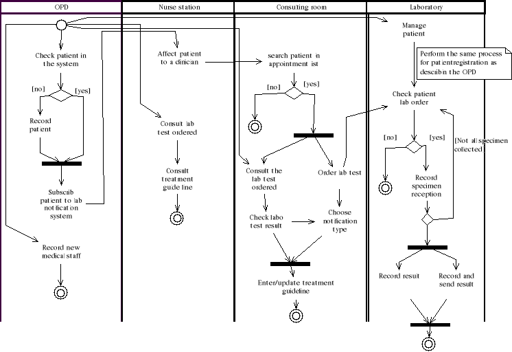
Figure3.3: Activity diagram
Use case diagrams
Since one of the goals in the systems development project is
to create usable software, it is important to clearly determine the user's
needs. Use cases help to understand and clarify the users' required
interactions with the system by illustrating the interactions between users and
business function to perform an activity in the workflow process. (Dennis et
al., 2012) To allow the better view of the use case diagram we will split the
use case diagram into three subsystem:
1. The authentication subsystem
2. The patient and medical staff management subsystem
3. The laboratory order management subsystem
4. The laboratory result management subsystem
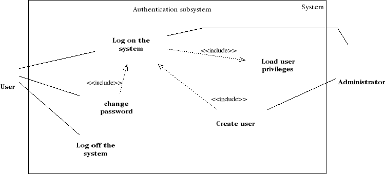 Figure 3.4: Use case diagram for authentication
subsystem Figure 3.4: Use case diagram for authentication
subsystem
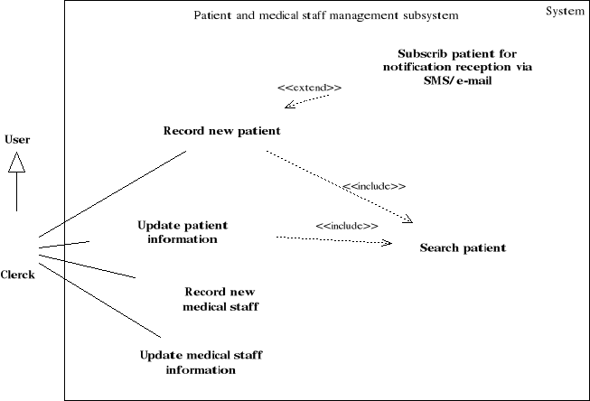
Figure3.5: Use case diagram for patient and medical
staff management subsystem
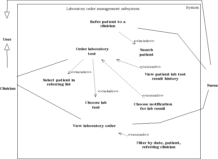
Figure 3.6: Use case diagram for the laboratory test
order management subsystem
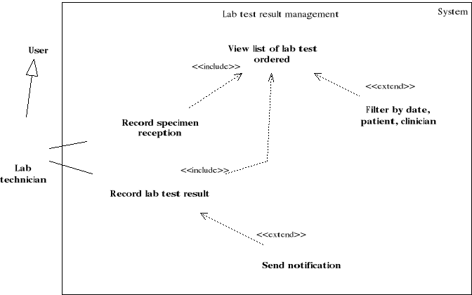 Figure 3.7: Use case diagram for the laboratory test result
management subsystem Figure 3.7: Use case diagram for the laboratory test result
management subsystem
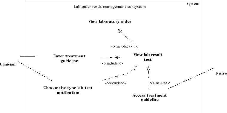
Figure3.8: Use case diagram for the lab order result
management subsystem
| 

