Class diagrams
The structure view of UML language is the most used to specify
an application requirements. The main objective of this view is to model the
structure of different classes of an object oriented (OO) application and their
interaction.(Blanc & Mounier, 2006)The main building block of a class
diagram is the class, which stores and manages information in the system. The
classes refer to the people, places, events, and things about which the system
will capture and process data. Later, during coding phase, classes can refer
also to coding-specific component like windows, forms, and other objects used
to construct the system.(Dennis et al., 2012)
To make the diagrams easier to read and keep the models at a
reasonable level of complexity, the classes is grouped into packages. In our
diagrams, only mains attributes are illustrates to make the diagram as simple
as possible and classes methods are not illustrates since they are more useful
during the coding phase. We will devise the class diagram to three package:
1. The user management package
2. The location package
3. The laboratory order and result management package
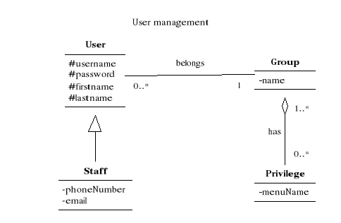
Figure3.9: Class diagram for the user's management
package
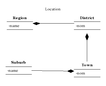
Figure3.10: Class diagram for the location
package
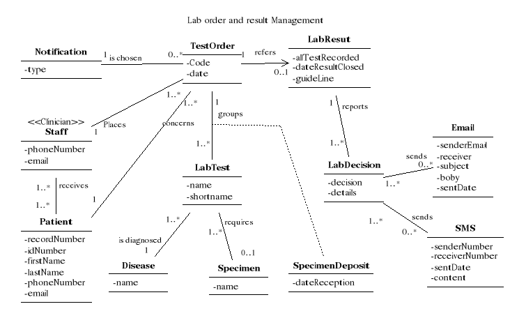
Figure3.11: Class diagram for the order and result
management package
Sequences diagrams
The behavioural aspect of an OO application is defined by the
way the objects of the system are interacting between them. The execution of
the program is essentially the exchange of the messages between application
objects to perform a particular treatment. (Blanc & Mounier, 2006)Since
sequence diagrams emphasize the time-based ordering of the interactions that
takes place among a set of objects, they are very helpful for understanding
real-time specifications and complex use cases.(Dennis et al., 2012)
We will focus on sequence diagrams of the most important use
cases to make our design simple: Order laboratory test and record laboratory
test result. The others sequences diagrams are also important but they will not
be illustrated to simplify the process modelling as they are more related to
the coding of system features.
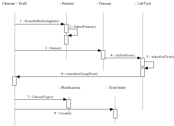
Figure3.12: Sequence diagram for order laboratory test
scenario
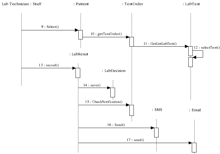
Figure3.13: Sequence diagram for record lab test
result scenario
| 

