An internet work is a collection of individual networks,
connected by intermediate networking devices, that functions as a single large
network. The networking devices are the vital tools for communication.
Whenever they have a set of computers or networking devices to
be connected, they make the connections, depending on the physical layout and
their requirements Depending on the physical layout or topology of the network,
there are many types of networks topologies, but in this project let talk about
Local Area Network(LAN) and Wide Area Network(WAN).
A router is a device that forwards data packets along
networks. A router is connected to at least two networks, commonly two LANs or
WANs or a LAN and its ISP's network. Routers are located at gateways, the
places where two or more networks connect.
Routers use headers and forwarding tables to determine the
best path for forwarding the packets, and they use protocols such as ICMP to
communicate with each other and configure the best route between any two hosts.
2
A switch is used in a wired network to connect Ethernet cables
from a number of devices together. The switch allows each device to talk to the
others. (Switches aren't used in networks with only wireless connections, since
network devices such as routers and adapters communicate directly with one
another, with nothing in between.)3
The Local Area Network (LAN) is by far the most common type of
data network. As the name suggests, a LAN serves a local area (typically the
area of a floor of a building, but in some cases spanning a distance of several
kilometers).
Typical installations are in industrial plants, office
buildings, college or university campuses, or similar locations. In these
locations, it is feasible for the owning Organization to install high quality,
high-speed communication links interconnecting nodes. Typical data transmission
speeds are one to 100 megabits per second.
A wide variety of LANs have been built and installed, but a
few types have more recently become dominant. The most widely used LAN system
is the Ethernet system developed by the Xerox Corporation.
Intermediate nodes (i.e. repeaters, bridges and switches)
allow LANs to be connected together to form larger LANs. A LAN may also be
connected to another LAN or to WANs and MANs using a "router".
· local (i.e. one building or group of buildings)
· controlled by one administrative authority
· assumes other users of the LAN are trusted
· usually high speed and is always shared
3
http://kbserver.netgear.com/kb_web_files/n101528.asp,
February 1, 2007
LANs allow users to share resources on computers within an
organization, and may be used to provide a (shared) access to remote
organizations through a router connected to a Metropolitan Area Network (MAN)
or a Wide Area Network (WAN).4
II.1.3. WAN
The term Wide Area Network (WAN) usually refers to a network
which covers a large geographical area, and use communications circuits to
connect the intermediate nodes. A major factor impacting WAN design and
performance is a requirement that they lease communications circuits from
telephone companies or other communications carriers.
Numerous WANs have been constructed, including public packet
networks, large corporate networks, military networks, banking networks, stock
brokerage networks, and airline reservation networks.
Some WANs are very extensive, spanning the globe, but most do
not provide true global coverage. Organizations supporting WANs using the
Internet Protocol are known as Network Service Providers (NSPs). These form the
core of the Internet.
By connecting the NSP WANs together using links at Internet
Packet Interchanges (sometimes called "peering points") a global communication
infrastructure is formed. NSPs do not generally handle individual customer
accounts (except for the major corporate customers), but instead deal with
intermediate organizations whom they can charge for high capacity
communications.
They generally have an agreement to exchange certain volumes
of data at a certain "quality of service" with other NSPs. So practically any
NSP can reach any other NSP, but may require the use of one or more other NSP
networks to reach the required destination. NSPs vary in terms of the transit
delay, transmission rate, and connectivity offered.
4
http://www.erg.abdn.ac.uk/users/gorry/course/intro-pages/lan.html
, September 12,2006
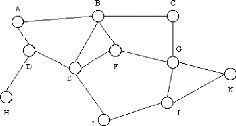
Figure 1: WAN topology (Typical "mesh" connectivity of a
Wide Area Network) Source:
http://www.erg.abdn.ac.uk/users/gorry/course/intro-pages/wan.html,september
22,2006
A typical network is shown in the figure above. This connects
a number of End System (ES) (e.g. A, C, H, K) and a number of Intermediate
Systems (IS)(e.g. B, D, E, F, G, I, J) to form a network over which data may be
communicated between the End Systems (ES).
The characteristics of the transmission facilities lead to an
emphasis on efficiency of communications techniques in the design of WANs.
Controlling the volume of traffic and avoiding excessive delays is important.
Since the topologies of WANs are likely to be more complex than those of LANs,
routing algorithms also receive more emphasis.
Many WANs also implement sophisticated monitoring procedures
to account for which users consume the network resources. This is, in some
cases, used to generate billing information to charge individual
users.5
II.1.4. MAN
Short for Metropolitan Area
Network, a data network designed for a town or city.
In terms of geographic breadth, MANs are larger than local-area networks
(LANs), but smaller than widearea networks (WANs). MANs are usually
characterized by very high-speed connections using fiber optical cable or other
digital media. 6
5
http://www.erg.abdn.ac.uk/users/gorry/course/intro-pages/wan.html,
September 12,2006
6
http://www.webopedia.com/TERM/M/MAN.html,
September 12,2006
II.1.5. SWITCHING II.1.5.1.
CIRCUITSWITCHING
Circuit switching is the most familiar technique used to
build a communications network. It is used for ordinary telephone calls. It
allows communications equipment and circuits, to be shared among users. Each
user has sole access to a circuit (functionally equivalent to a pair of copper
wires) during network use. Consider communication between two points A and D in
a network. The connection between A and D is provided using (shared) links
between two other pieces of equipment, B and C.
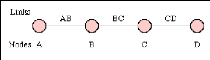
Figure 2: A connection between two systems A & D
formed from 3 links
Source:
http://www.erg.abdn.ac.uk/users/gorry/course/intro-pages/cs.html,
September 12, 2006
Network use is initiated by a connection phase, during which
a circuit is set up between source and destination, and terminated by a
disconnect phase. These phases, with associated timings, are illustrated in the
figure below.
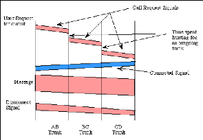
Figure 3: A circuit switched connection between A and
D
Source:
http://www.erg.abdn.ac.uk/users/gorry/course/intro-pages/cs.html,
September 12, 2006
Figure 3 shows how Information is flowing in two directions.
Information sent from the calling end is shown in pink and information returned
from the remote end is shown in blue.
After a user requests a circuit, the desired destination
address must be communicated to the local switching node (B). In a telephony
network, this is achieved by dialing the number.
Node B receives the connection request and identifies a path
to the destination (D) via an intermediate node (C). This is followed by a
circuit connection phase handled by the switching nodes and initiated by
allocating a free circuit to C (link BC), followed by transmission of a call
request signal from node B to node C. In turn, node C allocates a link (CD) and
the request is then passed to node D after a similar delay.
The circuit is then established and may be used. While it is
available for use, resources (i.e. in the intermediate equipment at B and C)
and capacity on the links between the equipment are dedicated to the use of the
circuit.
After completion of the connection, a signal confirming
circuit establishment (a connect signal in the diagram) is returned; this flows
directly back to node A with no search delays since the circuit has been
established. Transfer of the data in the message then begins. After data
transfer, the circuit is disconnected; a simple disconnect phase is included
after the end ofthe data transmission.
Delays for setting up a circuit connection can be high,
especially if ordinary telephone equipment is used. Call setup time with
conventional equipment is typically on the order of 5 to 25 seconds after
completion of dialing. New fast circuit switching techniques can reduce delays.
Trade-offs between circuit switching and other types of switching depend
strongly on switching times. 7
II.1.5.2. PACKET SWITCHING
Packet switching is similar to message switching using short
messages. Any message exceeding a network-defined maximum length is broken up
into shorter units, known as packets, for transmission; the packets, each with
an associated header, are then transmitted individually through the network.
The fundamental difference in packet communication is that the data is formed
into packets, and well-known "idle" patterns which are used to occupy the link
when there is no data to be communicated.
Packet network equipment discards the "idle" patterns between
packets and processes the entire packet as one piece of data. The equipment
examines the packet header information (PCI) and then either removes the header
(in an end system) or forwards the packet to another system. If the out-going
link is not available, then the packet is placed in a queue until the link
becomes free. A packet network is formed by links which connect packet network
equipment.
7
http://www.erg.abdn.ac.uk/users/gorry/course/intro-pages/cs.html,
September 12,2006
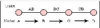
Figure 4: Communication between A and D using circuits
which shared dusing PS. Source: Own drawing
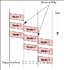
Figure 5: Packet-switched communication between systems
A and D Source:
http://www.erg.abdn.ac.uk/users/gorry/course/intro-pages/ps.html
Figure 5 illustrate how message has been broken into three parts
labeled 1 to 3 There are two important benefits from packet switching.
1. The first and most important benefit is that since packets
are short, the communication links between the nodes are only allocated to
transferring a single message for a short period of time while transmitting
each packet. Longer messages require a series of packets to be sent, but do not
require the link to be dedicated between the transmission of each packet. The
implication is that packets
belonging to other messages may be sent between the packets
of the message being sent from A to D. This provides a much fairer sharing of
the resources of each ofthe links.
2. Another benefit ofpacket switching is known as
"pipelining". Pipelining is visible in the figure above. At the time packet 1
is sent from B to C, packet 2 is sent from A to B; packet 1 is sent from C to D
while packet 2 is sent from B to C, and packet 3 is sent from A to B, and so
forth. This simultaneous use of communications links represents a gain in
efficiency; the total delay for transmission across a packet network may be
considerably less than for message switching, despite the inclusion of a header
in each packet rather than in each
8
message.
II.2 OSI MODEL AND TCP/IP II.2.1 THE SE VEN LAYERS MODEL
Seven layers are defined:
Application: Provides different services to
the applications and describes how real work actually gets done. This layer
would implement file system operations.
Presentation: Converts the information and
describes the syntax of data being transferred. This layer describes how
floating point numbers can be exchanged between hosts with different math
formats.
Session: Handles problems which are not
communication issues and describes the organization of data sequences larger
than the packets handled by lower layers. This layer describes how request and
reply packets are paired in a remote procedure call.
Transport: Provides end to end communication
control and describes the quality and nature of the data delivery. This layer
defines if and how retransmissions will be used to ensure data delivery.
8
http://www.erg.abdn.ac.uk/users/gorry/course/intro-pages/ps.html,September
12,2006
Network: Routes the information in the
network and describes how a series of exchanges over various data links can
deliver data between any two nodes in a network. This layer defines the
addressing and routing structure of the Internet.
Data Link: Provides error control between
adjacent nodes and describes the logical organization of data bits transmitted
on a particular medium. This layer defines the framing, addressing and check
summing of Ethernet packets.
Physical: Connects the entity to the
transmission media and describes the physical properties of the various
communications media, as well as the electrical properties and interpretation
of the exchanged signals. This layer defines the size of Ethernet coaxial cable
and the termination method.9
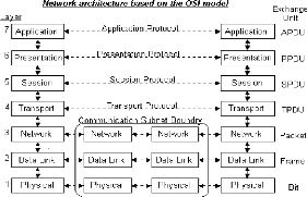
Figure 6: OSI model
Source:
http://www.raduniversity.com/networks/1994/osi/layers.htm,
september 22,2006
II.2.2 TCP/IP AND UDP PROTOCOLS
Even TCP and UDP use the same network layer (IP), TCP
provides a totally different service to the application layer than UDP does.TCP
provides a connection-oriented, reliable, byte stream service.
9
http://www.raduniversity.com/networks/1994/osi/layers.htm
,September 24, 2006
The term connection-oriented means the two applications using
TCP (normally considered a client and a server) must establish a TCP connection
with each other before they can exchange data. The typically analogy is dialing
a telephone number, waiting for the other party to answer the phone and say
something.
II.2.2.1 TCP
TCP is one of the main protocols in TCP/IP networks. Whereas
the IP protocol deals only with packets, TCP enables two hosts to establish a
connection and exchange streams of data. TCP guarantees delivery of data and
also guarantees that packets will be delivered in the same order in which they
were sent. In brief, TCP provide a reliable, connection-oriented, byte-stream,
transport layer service.10
II.2.2.1.1 Internet Protocol (IP)
The Internet Protocol (IP) is a network-layer (Layer 3)
protocol that contains addressing information and some control information that
enables packets to be routed. IP is the primary network-layer protocol in the
Internet protocol suite.
Along with the Transmission Control Protocol (TCP), IP
represents the heart of the Internet protocols. IP has two primary
responsibilities: providing connectionless, best-effort delivery of datagrams
through an internetwork; and providing fragmentation and reassembly of
datagrams to support data links with different maximum-transmission unit (MTU)
sizes.11
10
http://www.webopedia.com/TERM/T/TCP.html,
September 12,2006
11
http://www.cisco.com/univercd/cc/td/doc/cisintwk/ito_doc/ip.htm#wp4145,
September 24, 2006
II.2.2.1.2 IP Packet Format
An IP packet contains several types of information, as
illustrated in.
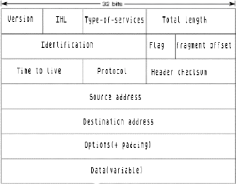
Figure 7: IP packet Datagram Source: Own
drawing
The following discussion describes the IP packet fields
illustrated in:
· Version--indicates the
version of IP currently used.
· IF Header Length
(IHL)--Indicates the datagram header length in 32-bit
words.
· Type-of-Service--Specifies how
an upper-layer protocol would like a current datagram to be handled, and
assigns datagrams various levels of importance.
· Total Length--specifies the
length, in bytes, of the entire IP packet, including the data and header.
· Identification--contains an
integer that identifies the current datagram. This field is used to help piece
together datagram fragments.
· Flags--consist of a 3-bit
field of which the two low-order (least-significant) bits control
fragmentation. The low-order bit specifies whether the packet can be
fragmented. The middle bit specifies whether the packet is the last fragment in
a series of fragmented packets. The third or high-order bit is not used.
· Fragment Offset--indicates
the position of the fragment's data relative to the beginning of the data in
the original datagram, which allows the destination IP process to properly
reconstruct the original datagram.
· Time-to-Live--maintains a
counter that gradually decrements down to zero, at which point the datagram is
discarded. This keeps packets from looping endlessly.
· Protocol--Indicates which
upper-layer protocol receives incoming packets after IP processing is
complete.
· Header Checksum--helps ensure
IP header integrity.
· Source
Address--specifies the sending node.
· Destination Address--specifies
the receiving node.
· Options--Allows IP to support
various options, such as security.
· Data--Contains upper-layer
information.
II.2.2.1.3 IP Addressing
As with any other network-layer protocol, the IP addressing
scheme is integral to the process of routing IP datagrams through an
internetwork. Each IP address has specific components and follows a basic
format. These IP addresses can be subdivided and used to create addresses for
subnetworks, as discussed in more detail later in this chapter.
Each host on a TCP/IP network is assigned a unique 32-bit
logical address that is divided into two main parts: the network number and the
host number. The network number identifies a network and must be assigned by
the InterNIC (Internet Network Information Center) if the network is to be part
ofthe Internet.
An ISP (Internet Service Provider) can obtain blocks of
network addresses from the InterNIC and can itself assign address space as
necessary. The host number identifies a host on a network and is assigned by
the local network administrator.
II.2.2.1.4 IP Address Format
The 32-bit IP address is grouped eight bits at a time,
separated by dots, and represented in decimal format (known as dotted decimal
notation). Each bit in the octet has a binary weight (128, 64, 32, 16, 8, 4, 2,
1). The minimum value for an octet is 0, and the maximum value for an octet is
255 Illustrates the basic format of an IP address.


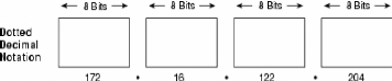
Figure 8: IP address consists of 32 bits, grouped into
four octets. Source:
http://www.cisco.com/univercd/cc/td/doc/cisintwk/ito_doc/ip.htm,September
24, 2006
II.2.2.2 UDP
UDP is a simple, datagram-oriented, transport layer protocol:
each output operation by a process produces exactly one UDP datagram, which
causes one IP datagram to be sent. This is different from a stream-oriented
protocol such as TCP where the amount of data written by an application may
have little relationship to what actually gets sent in a single IP datagram.
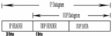
Figure 9: UDP encapsulation Source: Own
drawing
II.2.2.2.1 UDP Segment Structure
The UDP segment structure, shown in Figure 10
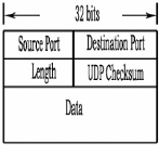
Figure 10: UDP segment structure
The application data occupies the data field of the UDP
datagram. For example, for DNS, the data field contains either a query message
or a response message. For a streaming audio application, audio samples fill
the data field. The UDP header has only four fields, each consisting of four
bytes.
As discussed in the previous section, the port numbers allow
the destination host to pass the application data to the correct process
running on that host (i.e., perform the demultiplexing function). The checksum
is used by the receiving host to check if errors have been introduced into the
segment during the course of its transmission from source to destination.
II.2.2.2.2 UDP Checksum
The UDP checksum covers the UDP header data. Recall that the
checksum in the IP header only covers the IP header; it does not cover any data
in the IP datagram. Both TCP and UDP have checksums in their headers to cover
their and their data. With UDP the checksum is optional, while it is
mandatory.


