CHAP 3 ANTENNA ARRAYS AND BEAM FORMING
3.1 Antenna Arrays
3.1.1 Introduction
A directional radiation pattern can be produced when several
antennas are arranged in spaced or interconnected. Such an arrangement of
multiple radiating elements is referred to as an array antenna, or plainly, an
array.
Instead of a single large antenna, many small antennas can be
used in an array to achieve a similar level of performance. The mechanical
problems associated with a single large antenna are traded for the electrical
problems of feeding several small antennas. With the advancements in solid
state technology, the feed network required for array excitation is of improved
quality and reduced cost [10].
Arrays offer the unique ability of electronic scanning of the
main beam, which can be
achieved by altering the phase of the exciting currents in
each element antenna of the
array. Thus, it enables the capability of scanning the
radiation pattern through space.
The array is hereby known as a phased array. Arrays can be of
any form of geometrical
configurations and antenna arrays include the Linear
Array, Planar Array and Circular
Array [23].
The overall field of the array is determined by the vector
addition of the fields radiated by the individual elements and this assumes
that the current in each element is the same as that of the isolated element.
In order to render a very directive pattern, it is essential that the fields
from the elements of the array interfere constructively in the required
directions and interfere destructively in the remaining space.
There are five factors that contribute to the shaping of the
overall pattern of antenna array with identical elements and there are:
§ Geometrical configuration of the array (linear,
circular, rectangular, etc)
§ Displacement between the elements
§ Excitation amplitude of individual elements
§ Excitation phase of individual elements
§ Relative pattern of the individual elements
Some of the above mentioned parameters will thus be used for
our simulations analysis.
In addition, this project will only be covering on linear and
planar arrays.
3.1.2 Theoretical
model for an antenna array
3.1.2.1 Linear array antenna
A linear array of discrete elements is an
antenna consisting of several individuals and indistinguishable elements whose
centers are finitely separated and fall on a straight line
[23]. One dimension uniform linear array is mere and the most
frequently used geometry with the array elements being spaced equally. Fig
(3.1) shows a typical linear array of micro strip antennas, which is one of the
emphases in this final project.
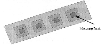
Fig
3.1: Linear array of micro strip [5].
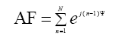
The total field of the array is equal to the field of a single
element positioned at the origin multiple by a factor which is widely known as
the array factor (AF).
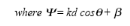
The array factor is a function of geometry of the array and
the excitation phase. By varying the separation d and/or the phase
â between the elements, the characteristics of the array factor
and the total field of the array can be controlled [5]. In other words, the
far-zone field of a uniform array with any number of identical elements is:
E(total) = [E(single element at reference point)] X [array
factor] (3.1)
Every array will have its own array factor and thus, the array
factor is generally a function of the number of elements, geometrical sequence,
relative magnitudes, relative phases and the inter-element spacing.
Nevertheless, elements having identical amplitudes, phases and spacing will
result in an array factor of simpler form.
Assuming a N elements array with identical amplitudes
but each succeeding element has a â progressive phase lead
current excitation relative to the preceding one (â represents
the phase by which the current in each element leads the current of the
preceding element). The array factor can thus be obtained by considering the
elements to be point sources. However, if the actual elements are not isotropic
sources, the total field can be form by multiplying the array factor of the
isotropic sources by the field of a single element, which is given by:
 (3.2)
(3.2)
and since the total array factor for the array is a summation
of exponentials, it can be
represented by the vector sum of N phasors each of
unit amplitude and progressive
phase  relative to the previous one [5].
| 

