3.1.3. Elements spacing
The inter-element spacing between the antenna elements is an
important factor in the design of an antenna array. If the elements are more
than ë/2 apart, then the grating lobes appear which degrades the
array performances.
Mutual coupling is an effect that limits the inter-element
spacing of an array. If the elements are spaced closely (typically less than
ë/2), the coupling effects will be larger and generally tend to
decrease with increase in the spacing. Therefore, the elements have to be far
enough to avoid mutual coupling and the spacing has to be smaller than
ë/2 to avoid grating lobes. For all practical purposes, a spacing
of ë/2 is preferred [25].
3.1.4. Microstrip patch antennas design
In the last decade, the patch antenna has become a strong
candidate for the use of the base stations for mobile communication. The patch
is made on a microstrip substrate, and though is an antenna which is easy to
fabricate to handle.
From [22], it is reported that the basic principal of the
patch antenna, is to get electrical fields of the antenna to combine in-phase
in the perpendicular direction of the patch.
For forming an antenna array with a number of patch antennas,
the distance between them is normally given in wavelengths. Some of parameters
constrain for the design, include the length and width of the antenna patch,
the type of substrate used and the substrate thickness. The dimensions of a
rectangular patch antenna can be determined using the following equations as
reported in [22].
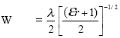 where
W is Width, (3.13) where
W is Width, (3.13)
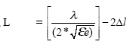 where L is Length (3.14) where L is Length (3.14)
where the effective dielectric constant,
åe and ?l ?are given by:
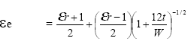 (3.15)
where åe is the effective dielectric and t is
the thickness of the substrate.
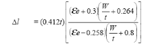 (3.16)
Wavelength, ë?= C/f
Where C is the speed of light, and f is the resonant
frequency.
| 

