Study of Smart Antenas on Mobile Communications( Télécharger le fichier original )par Ismaël NDAMUKUNDA Université Nationale du Rwanda - Ingéniorat (Bac + 5) en Telecom 2006 |

List of TablesTable 1 :Results of varying number of elements 38 Table 2: Results of varying side lobe level 40 Table 3 : Results of varying inter-element spacing 43
List of AbbreviationsMATLAB: Matrix Laboratory GSM:Global System for Mobile Communications (Ex Groupe Spéciale Mobile). RF: Radio Frequency BER: Bit Error Rate EM: Electromagnetic DSP: Digital Signal Processor SBA: Switching Beam Array TBA: Tracking Beam Array CDMA: Code Division Multiple Access SDMA: Space Division Multiple Access TDMA: Time Division Multiple Access FDMA: Frequency Division Multiple Access TDD: Time Division Duplex FDD: Frequency Division Duplex AF: Array Factor RLS: Recursive Least Square LMS: Least Mean Square DOAs: Directions of Arrival INTRODUCTIONIt is foreseen that in the future an enormous increase in traffic will be experienced for mobile and personal communications systems. This is due both to an increased number of users as well as new high bit rate data services being introduced. The increase in traffic will put a demand on both manufacturers and operators to provide high capacity systems in the networks. Presently, the only mobile communication campany in Rwanda is MTN Rwandacell. This company uses either omnidirectional in the sparsely populated areas or sectorized antennas in the densely populated areas - in the cities at its base stations. The basic challenge in wireless communication being the finite spectrum or bandwidth, the only technology believed to be the latest major technological innovation that has the capability of containing large increase in mobile communication systems access [1] is the smart antenna. Therefore, the aim of this project is to analyse and study smart antenna system, but also how the system can increase capacity in mobile communications. Our project is limited to an examination of the design of a smart antenna system for the base station for mobile communication. We show that the smart antennas can be implemented at the base station site, without requiring any changes neither at adjacent base stations nor in the mobile stations. Cost estimation of design is not included in this project. The project begins with antennas analysis and discusses the evolution from omni directional to smart antennas. Smart antenna system is presented in the second chapter in which keys benefits, signal propagation, uplink and downlink processing, and handling of common channel are also discussed. The third chapter consists of antenna array and beam forming. Multiple access schemes are discussed in chapter four. This is followed by the analysis and simulation on array antenna in chapter five and finally the conclusion and recommendations are given. CHAP 1 TOWARD SMART ANTENNA1.1 Antenna synthesisIn the business and industries worldwide, communications has become the key to momentous changes as they themselves adjust to the shift toward an information economy. Antennas provide mother earth a solution to a mobile communication system. In [2] it is reported that the antenna is a means of coupling electromagnetic energy from a transmission line into free space, thus allowing a transmitter to radiate, and a receiver to receive the incoming electromagnetic power. It is a passive device and therefore, the power radiated by a transmitting antenna cannot be greater than the power entering to the transmitter. In addition to transmitting and receiving energy, an antenna in an advance mobile system is generally required to optimize or accentuate the radiation energy in a particular direction while suppressing it in others. Physical size may vary greatly and antennas can be just a lens, an aperture, a patch, an assembly of elements (array), a reflector, or even a piece of conducting wire [3]. The antenna is one of the most critical elements for mobile communication systems and a good design of the antenna can ease system requirements and improve overall system performance. Practically, it is often necessary to design an antenna system that produce desired radiation characteristics. In general, there are common demands to design antenna whose far-field pattern posses nulls in certain directions or to yield pattern that exhibit a desired distribution, narrow beamwidth and low side lobes, decaying minor lobes, and so forth. Hence, antenna synthesis is an approach that uses a systematic method or combination of methods to arrive at an antenna configuration which yields a pattern that is either exactly or approximately the same to the initial specified pattern, while satisfying other system constrains. From [4], antenna pattern synthesis can be classified into three categories. The first group that normally utilizes the Schelkunoff Method requires the antenna patterns to possess nulls in certain desired direction. The next category, which requires the patterns to exhibit a desired distribution in the entire visible region, is referred to beam shaping. It can be achieved by using the Fourier Transform and Woodward-Lawson Methods. Finally, the Binomial Technique and Dolph-Chebyshev Method are usually used to produce radiation patterns with narrow beamwidth and low side lobes. However, only the Woodward-Lawson method and the Dolph-Chebyshev method are discussed. 1.1.1 Woodward-Lawson MethodA popular antenna pattern synthesis method was introduced by Woodward and Lawson. The synthesis is accomplished by sampling the desire pattern at various discrete locations. Each pattern sample is associated with a harmonic current of uniform amplitude distribution and uniform progressive phase, whose corresponding field is known as a composing function. Each composing function for a linear array is as shown in (1.1)
N - Number of elements bm - excitation coefficient Öm - Phase excitation The excitation coefficient bm of every harmonic current is such that its field strength is similar to the amplitude of the desired pattern at its corresponding sampled point. The total excitation of the source is comprised of a finite summation of space harmonic, and the corresponding synthesized pattern is represented by a finite summation of composing functions with each term representing the field of a current harmonic with uniform amplitude distribution and uniform progressive phase [5]. The overall pattern produced by this method is described as follows. The first composing function yields a pattern whose main beam position is decided by the value of its uniform progressive phase with the innermost side lobes level approximately -13.5dB,and while the rest of the side lobes decreases monotonically. Having a similar pattern, the second composing function will adjust its uniform progressive phase so that its main lobe corresponds to the innermost nulls of the first composing function. This will contribute to the filling-in of the innermost null of the first composing function pattern, in which, the amount of filling-in is restrained by the amplitude excitation of the second composing function. Thus, this procedure will carry on for the remaining finite number of composing functions. When Woodward-Lawson method is implemented to synthesized discrete linear arrays, the pattern of each sample is
d - inter-element spacing k - constant è - angle l= Nd assumes the array is equal to the length of the line source. The overall array factor can be written as a superposition of 2M or 2M+1 terms each of the form of (1.2) [5]. Therefore Array Factor is defind as
Generally, although Woodward-Lawson synthesis technique reconstructs pattern whose values at the sampled points are similar to the ones of the desired signal, it is unable to control the pattern between the sample points. The quality of fit to the desired pattern fd(w) by the synthesis pattern f(w) over the main beam is measured by the ripple, R, which is defined as
over the main beam. Also of interest is the region between the main beam and side lobe region, referred to as the transition region. It is desirable to have the main beam fall off shapely into the side lobe region. Thus, the transition width T is introduced and defined as Where wf=0.9 and wf=0.1 are the values of w where the synthesized pattern f equals 90% and 10% of the local discontinuity in the desired pattern [6]. |
|


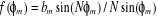 (1.1)
(1.1)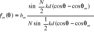 (1.2)
(1.2)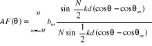 (1.3)
(1.3)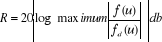 (1.4)
(1.4) (1.5)
(1.5)