1.2 Evolution from Omni directional to Smart Antennas
In [7], an antenna in telecommunications system is defined as
a port through which radio frequency (RF) energy is coupled from the
transmitter to the outside world for transmission purposes, and in reverse, to
the receiver from the outside world for reception purposes. To date, antennas
have been the most neglected of all the components in personal communications
systems. Yet, the manner in which radio frequency energy is distributed into
and collected from space has a profound influence upon the efficient use of
spectrum, the cost of establishing new personal communications networks and the
service quality provided by those networks. The goal of the next several
sections is to answer to the question «Why to use anything more than a
single omni directional (no preferable direction) antenna at a base
station?» by describing, in order of increasing benefits, the principal
schemes for antennas deployed at base stations.
1.2.1 Omni directional Antennas
Since the early days of wireless communications, there has
been the simple dipole antenna, which radiates and receives equally well in all
directions (direction here being referred to azimuth). To find its users, this
single-element design broadcasts omni directionally in a pattern resembling
ripples radiation outward in a pool of water (Fig.1.1).
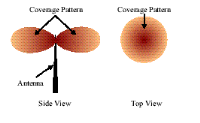
Fig.1.1 Omni directional Antennas and coverage patterns
[7].
While adequate for simple RF environments where no specific
knowledge of the users' whereabouts is either available or needed, this
unfocused approach scatters signals, reaching desired users with only a small
percentage of the overall energy sent out into the environment [8]. Given
this limitation, omni directional strategies attempt to overcome environmental
challenges by simply boosting the power level of the signals broadcast. In a
setting of numerous users (and interferers), this makes a bad situation worse
in that the signals that miss the intended user become interference for those
in the same or adjoining cells. In uplink applications (user to base station),
omni directional antennas offer no preferential gain for the signals of served
users. In other words, users have to shout over competing signal energy [9].
Also, this single-element approach cannot selectively reject signals
interfering with those of served users and has no spatial multipath mitigation
or equalization capabilities. Therefore, omni directional strategies directly
and adversely impact spectral efficiency, limiting frequency reuse. These
limitations of broadcast antenna technology regarding the quality, capacity,
and geographic coverage of mobile communication prompted an evolution in the
fundamental design and role of the antenna in a mobile communication system.
1.2.2 Directional Antennas and Sectorized Systems
A single antenna can also be constructed to have certain fixed
preferential transmission and reception directions. Sectorized antenna systems
take a traditional cellular area and subdivide it into sectors that are covered
using directional antennas looking out from the same base station location Fig.
1.2. Operationally, each sector is treated as a different cell in the system,
the range of which can be greater than in the omni directional case, since
power can be focused to a smaller area. This is commonly referred to as antenna
element gain. Additionally, sectorized antenna systems increase the possible
reuse of a frequency channel in such cellular systems by reducing potential
interference across the original cell. As many as six sectors have been used in
practical service, while more recently up to 16 sectors have been deployed
[10]. However, since each sector uses a different frequency to reduce co
channel interference, handoffs (handovers) between sectors are required.
Narrower sectors give better performance of the system, but this would result
in to many handoffs. While sectorized antenna systems multiply the use of
channels, they do not overcome the major disadvantages of standard omni
directional antennas such as filtering of unwanted interference signals from
adjacent cells.
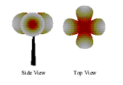
Fig
1.2: Sectorized antenna system and coverage pattern [10].
| 

