1.2.3 Smart antenna
The smart antenna systems, as shown in Fig 1.3, will be
introduced in order to improve systems performance by increasing spectrum
efficiency, extending coverage area, tailoring beam shaping, steering multiple
beams. Most importantly, smart antenna system increases long-term channel
capacity through Space Division Multiple Access scheme (See
Chapter 4 on Multiple Access Schemes).
In addition, it also reduces multipath fading, co channel
interferences, initial setup cost and bit error rate (BER).
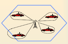
Fig 1.
3: Concept of smart antenna systems [8].
A smart antenna system is defined in [8] as
a system which uses an array of low gain antenna elements with a
signal-processing capability to optimize its radiation and/or reception pattern
automatically in response to the ever changing signal environment.
This can be visualized as the antenna focusing a beam towards
the communication user only.
Truly speaking, antennas are only mechanical construction
transforming free electromagnetic (EM) waves into radio frequency (RF) signals
traveling on a shielded cable or vice-versa. They are not smart but antenna
systems are. The whole system
consists of the radiating antennas, a combining/dividing
network and a control unit. The
control unit is usually realized using a digital signal
processor (DSP), which controls
several input parameters of the antenna to optimize the
communication link.
This show that smart antennas are more than just the
«antenna,» but rather a complete transceiver concept. Smart antenna
systems are customarily classified as either Switching- Beam Array (SBA) or
Adaptive Array (also known as Tracking-Beam Array - TBA) systems and they are
the two different approaches to realizing a smart antenna [1].
1.2.3.1 Switching-Beam Array (SBA)
In the smart antenna systems, the SBA approach forms multiple
fixed beams with
enhanced sensitivity in specific area. These antenna systems
will detect signal strength,
and select one of the best, predetermined, fixed beams for the
subscribers as they move
throughout the coverage sector. Instead of modeling the
directional antenna pattern with
the metallic properties and physical design of a single
element, a SBA system couple
the outputs of multiple antennas in such a manner that it
forms a finely sectorized
(directional) beams with spatial selectivity [10].
Fig 1.4 shows the SBA patterns and Fig 1.5 illustrated the
design network of a typical SBA system. The SBA system network illustrated is
relatively simple to implement, requiring only a beam forming network, a RF
switch, and control logic to select a specific beam.
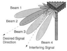
Fig
1.4 Switch-Beam Systems [11].
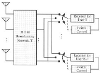
Fig
1.5: A Switch-Beam network [11].
Switched beam systems offer numerous advantages of more
elaborate smart antenna
systems at a fraction of the complexity and expense.
Nevertheless, there are some
limitations to switched beam array, which comprise of the
inability to provide any
protection from multipath components that arrive with
Directions-of-Arrival (DOAs)
near that of the desire components, and also the inability to
take advantage of path
diversity by combining coherent multipath components. Lastly,
due to scalloping, the
received power from a user may fluctuate when he moves around
the base station.
Scalloping is the roll-off of the antenna pattern as a
function of angles as the DOA
varies from the bore sight of each beam produced by the beam
forming network [11].
In spite of the drawbacks, SBA systems are widespread for
various reasons. They
provide some range extension benefits and offer reduction in
delay spread in certain
propagation environments. In addition, the engineering costs
to implement this low
technology approach are lesser than those associated with more
complicated systems.
| 

