CHAPTER FOUR
4.0 METHODOLOGY
The present chapter comprises two major sections describing the
watershed and streams characteristics method of determination and the water
balance modelling method.
4.1 Watershed and streams characteristics
The concept of a watershed is basic to all hydrologic designs.
Watershed has been defined as an area of land draining into a stream at a given
location (Chow et al, 1988). In other words and usually a watershed is defined
as the area that appears, on the basis of topography, to contribute all the
water that passes through a given cross section of a stream. The surface trace
of the boundary that delimits a watershed is called a divide, and the
horizontal projection of the area of a watershed is called the drainage area of
a stream at that cross section, while the location of the stream cross section
that defines the watershed is determined by the analysis.
Since large watersheds are made up of many smaller watersheds,
it is necessary to define the watershed in terms of a point. This point is
usually the location at which the design is being made and is referred to as
the watershed «outlet». With respect to the outlet, the watershed
consists of all land area that «sheds» water to the outlet during a
rainstorm. Using the concept that «water runs downhill», a watershed
is defined by all points enclosed within an area from which rain falling at
these points will contribute water to the outlet (McCuen, 2005).
To delineate the Congo River Watershed and streams network, a
Digital Elevation Model (DEM), HYDRO 1K with 1 km of spatial resolution, later
on described, was used and processed with Geographical Information System
packages viz Integrated Land and Water System (ILWIS) and ArcGIS.
In the following section are presented different steps
followed for the DEM-Hydro watershed processing. The purpose of this chapter is
to define and hydrogeomorphologically charcterise the watershed and streams
behaviours of the Congo basin, availing useful data sets for hydrological
modellings.
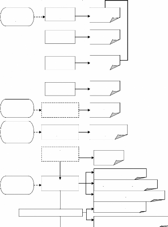
4.2 Watershed and drainage network Processing Method
The detailed processing method presented bellow (Figure 12) is
a combination of techniques used in GIS ILWIS 3.4, ArcINFO 9.2 and ArcView 3.2
packages; it consists in:
1 DEM visualization
2 Flow Determination (Fill sinks, Flow direction, Flow
accumulation, Flow
Modification)
3 Variable threshold computation
4 Network and Catchment Extraction (Drainage network extraction,
Drainage
network ordering, Catchment extraction, Catchment merge
5 Compound Parameter Extraction (Overland flow length, Compound
Index
calculation)
6 Statistical Parameter Extraction (Horton statistics, aggregate
statistics, cumulative
hypsometric curve, class coverage).
DEM
1 kHYDRO 30sec

Statatistical Parameters Extraction
HORTON statistics
Cumulative Hypsometric Curve

Threshold
Outlets coordinate
Digitized Drainage
Minimum Drainage
Length
Compound Parameters Extraction
Drainage Network Ordering
Catchment Extraction
Catchment Merge
Drainage Network Extraction
DEM Optm
DEM Fill Sinks
Flow Direc
Flow Accu
Drainage Network Ordering
Map
DEM Optm Map
DEM Filled Map
Flow Direct Map
Flow Accu Map
Drainage Map
Overland Flow length Map
Catchment Maps
Extract Stream Segments + Attributes
Wetness/Power/Sediment indexes Maps
Catchment Merged Map
Longest Flow Path Segment Map
Figure 12 DEM Processing flow chart: Extraction of
Drainage network, Catchment and Horton Parameters.
| 

