4.2. The inert gas
stripping technique
4.2.1. Chemicals
To validate the method, experiments were performed with NMP as
solvent whereas n-hexane, hex-1-ene, hex-1-yne, methanol, cyclohexane, benzene
and acetone were used as solutes in the ionic liquid
trihexyltetradecylphosphonium bis (trifluoromethylsulfonyl) imide, [3C6C14P]
[BTI]. Appendix C provides additional information about the solvents, including
their source, purity, density and refractive index. No further purification was
undertaken for the solutes as they were of high purity. Solvents were purified
by heat treatment under vacuum.
4.2.2. Experimental Set-up
As part of this study, it was intended to construct an entire
inert gas stripping set up with an equilibrium cell able to accommodate small
volumes of samples, less than 50 g. This was a necessity since ionic liquids
are very expensive chemicals. The second reason why a dilutor cell was needed
is for systems that are not suitable when using the GLC technique. Examples of
these are systems involving solutes that are solid at room temperature, solvent
mixtures and those leading to a very long retention time. Design parameters for
the dilutor cell were discussed in the previous chapter. The greatest part of
the design work was centered on the dilutor cell as it is the most determinant
piece of the set up performance. Figure 4-1 presents the simplified flow
diagram of the set up used in this study, which is similar to the one described
by Krummen et al. (2000) and Coquelet and Richon (2005). Photograph 4-2 gives
the experimental set up of the inert gas stripping apparatus.
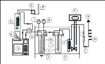
Figure 4-1: Flow diagram of the experimental
set up for the inert gas stripping method.
A-Helium, Nitrogen and air supply
for the GC; B- Nitrogen line; C-Valve; D- flow regulator; E-
Immersion
temperature controller; F-Coil tube (Heat exchanger); G-Transparent acrylic
bath; H- Dilutor
cell; I-Capillaries; J-Presaturation cell; K-Platinum
resistance thermometer; L-Pressure transducer; M-
Sampling valve; N-GC
apparatus; O-PC monitor; P-Cold trap; Q- Coil tube (Heat exchanger);
R-Soap
bubble flow-meter; S-Magnetic stirrer.
4.2.2.1. Gas cylinders
Four gases are used in this work:
· Nitrogen as stripping gas;
· Helium as carrier gas for the GC apparatus;
· Air and Hydrogen to produce the ignition flame for the GC
(FID only).
The four cylinders containing the above gases are fitted with
regulators. Nitrogen flow rate is controlled by a smaller regulator. Its value
is determined by means of a soap bubble flow meter.
4.2.2.2. Water bath
An 18-litre transparent acrylic water bath, with maximum
allowed temperature of 70 oC, was used to accommodate the cells
during experiments. During experiments, leaks could be easily detected by the
observation of gas bubbles, due to the transparency of the bath. A Haake
Difisons temperature controller kept the water in the bath at a constant
temperature set before each run. The nitrogen line (1/4 inch inner diameter and
12 m long) was coiled and immersed in the water bath to allow the gas to
equilibrate to the set-point temperature before entering the cells. In order to
reduce heat loss to the atmosphere, the water surface in the bath was
completely covered with polystyrene chips. The temperature stability of the
bath was #177;0.1 K.
4.2.2.3. Cells
The two glass cells are identical and have a total volume of
50 cm3 each. They were made for the purpose of this work by a Durban
glass blower, Mr. Peter Siegling. Metallic parts were manufactured and fitted
by the School of Chemical Engineering workshop staff members, Mr. Ken Jack and
Mr. Kelly Robertson. The shape is similar to the cells previously used by other
researchers (Coquelet and Richon 2005). Mass transfer considerations discussed
by Richon et al. (1980) were taken into account to determine the cell height
using equation (3-95), assuming
the degree of the equilibrium attainment = 0.99 From the
literature, ranges of different
properties related to FILs (See table 2-2) were used in
equation (3-95) to find out the most suitable height for the cell. The same
procedure was used by Li et al. (1993) to find out the optimum height of the
dilutor cell used in the study of IDAC`s for nonelectrolytes solutes in water.
For systems involving ionic liquids, the presaturator cell was removed. As
shown in Photograph 4-3, the dilutor cell is fitted with ten stainless steel
capillaries (0.1 mm inner diameter) purchased from Anatech, through which the
stripping gas is introduced. During experiments, they should be placed in such
a way that bubbles are not directed to the vortex. This will prevent bubbles
coalescence (George 2008). A class A Pt-100 temperature sensor (length 250 mm,
outer diameter 3 mm and limiting error of 0.25 oC) fitted with
stainless steel pot seal and a Sensotec pressure transducer are inserted in
order to measure the temperature of
the mixture and the pressure in the dilutor cell. To obtain
accurate readings, both sensors had to be calibrated. A CTH 6500 digital
thermometer (accuracy: #177;0.03 %) and a CPH 6000 pressure calibration
standard (accuracy: #177;0.1 %) for temperature and pressor sensor
calibrations, respectively. The bolt (G) along with the Teflon piece (H) seal
the cell to ensure that no portion of nitrogen flows through other channels
than the provided capillaries. Agitation of the solution contained in the cell
is achieved by means of a magnetic stirrer. Other features of the designed cell
are given by Photograph 4-3.
| 

